Jet JWBS-140S Скачать руководство пользователя страница 12


12 

Grounding Instructions 

 This Band Saw must be 

grounded while in use to protect the operator 
from electric shock. 

In the event of a malfunction or breakdown, 
grounding provides a path of least resistance for 
electric current to reduce the risk of electric 
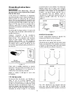
shock. This tool is equipped with an electric cord 
having an equipment-grounding conductor and a 
grounding plug that looks similar to the plug in 
Figure 10. The plug must be inserted into a 
matching outlet that is properly installed and 
grounded in accordance with all local codes and 
ordinances. 

Do not modify the plug provided.  If it will not fit 
the outlet, have the proper outlet installed by a 
qualified electrician. 

Improper connection of the equipment-
grounding conductor can result in a risk of 
electric shock.  The conductor, with insulation 
having an outer surface that is green with or 
without yellow stripes, is the equipment-
grounding conductor.  If repair or replacement of 
the electric cord or plug is necessary, do not 
connect the equipment-grounding conductor to a 
live terminal. 


Figure 10 

Check with a qualified electrician or service 
personnel if the grounding instructions are not 
completely understood, or if in doubt as to 
whether the tool is properly grounded.  

Repair or replace a damaged or worn cord 
immediately. 

115 Volt Operation 

As received from the factory, your bandsaw is 
ready to run at 115-volt operation. This 
bandsaw, when wired for 115 volts, is intended 
for use on a circuit that has an outlet and a plug 
that looks like the one illustrated in Figure 10. A 
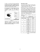
temporary adapter, like the adapter in Figure 11, 
may be used to connect this plug to a two-pole 
receptacle, as shown in Figure 11, if a properly 

grounded outlet is not available. The temporary 
adapter should only be used until a properly 
grounded outlet can be installed by a qualified 
electrician. This adapter is not applicable in 
Canada.  The green colored rigid ear, lug, or 
tab, extending from the adapter, must be 
connected to a permanent ground such as a 
properly grounded outlet box, as shown in 
Figure 11. 


Figure 11 

230 Volt Conversion 

If 230V, single-phase operation is desired, the 
following instructions must be followed: 

Disconnect machine from power source. 

This band saw is supplied with four motor leads 
that are connected for 115V operation, as shown 
in Figure 12.  Reconnect these four motor leads 
for 230V operation, as shown in Figure 12. 


Figure 12 

The 115V attachment plug supplied with the 
band saw must be replaced with a UL/CSA 
listed plug suitable for 230V operation, as shown 

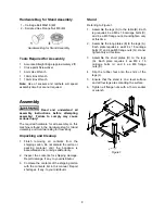
Содержание JWBS-140S

Страница 1: ...s Manual 14 inch Woodworking Band Saw Model JWBS 14OS WMH TOOL GROUP 2420 Vantage Drive Elgin Illinois 60123 Part No M 708113A Ph 800 274 6848 Revision B 03 06 www wmhtoolgroup com Copyright WMH Tool...

Страница 2: ...mination postage prepaid to a location designated by us For the name of the location nearest you please call 1 800 274 6848 You must provide proof of initial purchase date and an explanation of the co...

Страница 3: ...90 Table Stop 14 Changing Blades 14 Adjusting Blade Tension 15 Adjusting Blade Tracking 15 Adjusting Upper Blade Guide Assembly 16 Blade Guide Adjustment 16 Blade Support Bearing Adjustment 16 Option...

Страница 4: ...les of these chemicals are Lead from lead based paint Crystalline silica from bricks cement and other masonry products Arsenic and chromium from chemically treated lumber Your risk of exposure varies...

Страница 5: ...6 Use recommended accessories improper accessories may be hazardous 27 Maintain tools with care Keep saw blades sharp and clean for the best and safest performance Follow instructions for lubricating...

Страница 6: ...SFPM 3000 Table Size in 14x 14 Table Slot Size DxW in 3 8 x 3 4 Table Height From Floor in 44 Table Tilt deg 45 right 15 left Dust Port Diameter in 4 Overall Dimensions HxWxD in 68 x24x 26 1 2 Motor 3...

Страница 7: ...20 Short Support Plate 2 21 Long Support Plate 2 22 Rubber Foot 4 Hardware Bag for the Saw Body Contents of the Carton Hardware Bag for Saw Body 01 Wire Clip 1 02 Pan Head Screw M5x12 3 03 Hex Cap Scr...

Страница 8: ...l the bandsaw is assembled and is running satisfactorily 2 Inspect the contents for shipping damage Report damage if any to your distributor 3 Compare the contents of the shipping carton with the cont...

Страница 9: ...ight side of the saw insert the end of the motor with the shaft and pulley A through the opening B in the casting 2 Rest the motor on a section of 2x4 placed between the table and motor and against th...

Страница 10: ...e 6 1 With a cross point screwdriver fasten the switch A to the casting C with the two screws already on the switch box B These screws also hold the back plate of the switch box in place Note There ar...

Страница 11: ...the screw half way into the trunnion support bracket G Adjustment will be made later 4 Remove the table pin M and table insert L from the center opening 5 Orient the table so that the saw blade will p...

Страница 12: ...understood or if in doubt as to whether the tool is properly grounded Repair or replace a damaged or worn cord immediately 115 Volt Operation As received from the factory your bandsaw is ready to run...

Страница 13: ...ve three prong grounding plugs and three pole receptacles that accept the tool s plug Make sure the cord is in good condition and heavy enough to carry the current your band saw will draw An undersize...

Страница 14: ...s 90 degrees to the blade 4 If an adjustment is necessary loosen lock knobs tilt table to the right and lock in place 5 Loosen jam nut and turn table stop Figure 14 left or right to raise or lower the...

Страница 15: ...ore experienced with the saw you may find it necessary to change the blade tension from the initial setting Changes in blade width and the type of material being cut will have an effect on blade tensi...

Страница 16: ...ach and tighten the knob A Blade Guide Adjustment Never operate the Band Saw without all guards in place and in working order Referring to Figure 20 1 Disconnect machine from power source 2 Remove the...

Страница 17: ...025 709357 Premium alloy 1 2 93 1 2 6 Hook 0 025 709358 Premium alloy 3 4 93 1 2 3 Hook 0 032 709359 Premium alloy 3 4 93 1 2 10 Raker 0 035 709226 Premium alloy 1 8 105 14 Raker 0 025 709361 Premium...

Страница 18: ...5 blade and mounting instructions with parts list 708716 JMG 14 Miter Gauge Assembly For straight and angle cutting Includes guide bar pivoting support body and adjustable stops 708719 JRB 14 Blade Bl...

Страница 19: ...according to blade size Blade wanders during cut Guides not set properly Adjust guides Dull blade Replace blade Blade mounted wrong Teeth should face operator and point downward Gum or pitch on blade...

Страница 20: ...er M5 2 20 523028 Switch Box 1 21 150056 Switch Backing Plate 1 23 990821 Pan Head Screw M5x6 2 24 998654 Strain Relief 2 25 JWBS14OS 125 Power Cord 1 26 JWBS14OS 126 Motor Cord 1 27 998623 Strain Rel...

Страница 21: ...Post 1 80 150013A Thumb Screw M6x16 1 81 150015A Upper Spacing Sleeve 2 82 BB 6200ZZ Ball Bearing 6200ZZ 2 83 JWBS14OS 183 Retaining Ring S10 2 84 JWBS14OS 184 Guide Post 1 85 JWBS14OS 185 Support Br...

Страница 22: ...81 Steel Ball 1 119 150099 Spring 1 120 TS 1525011 Socket Set Screw M10x10 1 121 JWBS14OS 1121 Spring Nut M4 2 122 JWBS14OS 1122 Cord Clamp 1 124 TS 1482031 Hex Cap Screw M6x16 1 125 100018 Indicator...

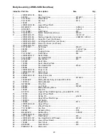
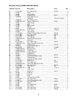
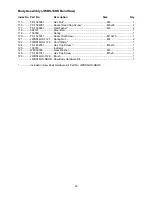
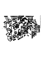
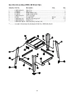
Страница 23: ...23 Body Assembly JWBS 14OS Band Saw...

Страница 24: ...tand Leg 4 3 612050W Support Plate long 2 4 612051W Support Plate short 2 5 JWBS14OS 205 JET Logo Label 1 6 991516 Carriage Bolt M8x16 40 7 JWBS14OS 174 Serrated Hex Flange Nut M8 40 8 JWBS14OS 208 Ru...

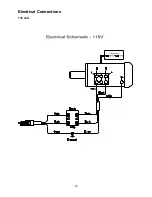
Страница 25: ...25 Electrical Connections 115 volt...

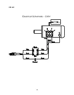
Страница 26: ...26 230 volt...

Страница 27: ...27 Notes...

Страница 28: ...28 WMH Tool Group 2420 Vantage Drive Elgin Illinois 60123 Phone 800 274 6848 www wmhtoolgroup com...

Отзывы: