background image


28.  Remove  loose  items  and  unnecessary  work 

pieces from the area before starting the tool. 

29.  Keep hands clear of the router bit area. Avoid 

awkward operations and hand positions where 
a  sudden  slip  could  cause  your  hand  to 
contact the cutting tool. 

30.  Use  push-sticks,  feather  boards,  or  jigs  when 

cutting small or narrow work pieces. 

31.  Do not touch a router bit immediately after use; 

it will be hot and may cause skin burns. 

32.  Don’t  use  in  dangerous  environment.  Don’t 

use  power  tools  in  damp  or  wet  location,  or 
expose  them  to  rain.  Keep  work  area  well 
lighted. 

33.  Keep  electrical  cord  away  from  sharp  edges, 

heat  or  moving  parts.  Position  cord  so  it  will 
not become a trip hazard. 

34.  Before using the Router Lift, read and become 

thoroughly  familiar  with  all  manufacturer’s 
operating 

and 

safety 

instructions 

that 

accompanied the router you will be using. 

35.  Make sure workpiece is free from nails or other 

foreign objects. 

36.  After  installing  a  bit,  make  sure  collet  is 

securely  tightened.    An  unsecured  bit  may  fly 
loose from the collet and cause injury. 

37.  Raise router bit to minimum height needed for 

cut; excess exposure of bit may create greater 
risk. 

38.  Use  proper  extension  cord.  Make  sure  your 

extension  cord  is  in  good  condition.  When 
using  an  extension  cord,  be  sure  to  use  one 
heavy enough to carry the current your product 
will draw. An undersized cord will cause a drop 
in  line  voltage  resulting  in  loss  of  power  and 
overheating.  Table  2 

(sect. 6.2)

  shows  the 

correct  size  to  use  depending  on  cord  length 
and nameplate ampere rating. If in doubt, use 
the  next  heavier  gage.  The  smaller  the  gage 
number, the heavier the cord. 


Familiarize yourself with the following safety notices used in this manual: 

 This means that if precautions are not heeded, it may result in minor injury and/or possible 

machine damage. 

 This means that if precautions are not heeded, it may result in serious, or possibly even fatal, 

injury. 

SAVE THESE INSTRUCTIONS 

2.0

  About this manual 

This  manual  is  provided  by  JET,  covering  assembly  and  maintenance  procedures  for  a  JET  Model  JRL-912 
Router Lift with Table and Stand. This manual contains instructions on installation, safety precautions, general 
operating  procedures,  maintenance  instructions  and  parts  breakdown.  Your  product  has  been  designed  and 
constructed to provide consistent, long-term operation if used in accordance with the instructions as set forth in 
this document.  

This  manual  is  not  intended  to  be  an  instruction  guide  for  routers  or  router  operation,  use  of  after-market 
accessories,  choice  of  stock,  etc.  Consult  the  documentation  that  accompanies  your  router.  Additional 
knowledge can be obtained from experienced users or trade articles. Whatever accepted methods are used, 
always make personal safety a priority. 

If there are questions or comments, please contact your local supplier or JET. JET can also be reached at our 
web site: www.jettools.com. 

Retain this manual for future reference. If the machine transfers ownership, the manual should accompany it. 

Register your product using the provided mail-in card or register online: http://www.jettools.com 


WARNING:

  Drilling,  sawing,  sanding  or 

machining wood products generates wood dust 
and  other  substances  known  to  the  State  of 
California  to  cause  cancer.  Avoid  inhaling  dust 
generated  from  wood  products  or  use  a  dust 
mask  or  other  safeguards  for  personal 
protection. 

Wood  products  emit  chemicals  known  to  the 
State  of  California  to  cause  birth  defects  or 
other  reproductive  harm.  For  more  information 
go to http://www.p65warnings.ca.gov/wood. 


WARNING:

 This product can expose you to 

chemicals including lead which is known to the 
State  of  California  to  cause  cancer  and  birth 
defects  or  other  reproductive  harm.  For  more 
information  go  to  http://www.p65warnings.ca. 
gov. 

Содержание JRL-912

Страница 1: ...s Manual Router Lift and accessories Model JRL 912 JET 427 New Sanford Road LaVergne Tennessee 37086 Part No M 737000 Ph 800 274 6848 Edition 3 03 2019 www jettools com Copyright 2017 JET 737000CK shown This pdf document is bookmarked ...

Страница 2: ... turning it on 14 Keep safety guards in place at all times when the machine is in use If removed for maintenance purposes use extreme caution and replace the guards immediately after completion of maintenance 15 Check damaged parts Before further use of the machine a guard or other part that is damaged should be carefully checked to determine that it will operate properly and perform its intended ...

Страница 3: ...jury and or possible machine damage This means that if precautions are not heeded it may result in serious or possibly even fatal injury SAVE THESE INSTRUCTIONS 2 0 About this manual This manual is provided by JET covering assembly and maintenance procedures for a JET Model JRL 912 Router Lift with Table and Stand This manual contains instructions on installation safety precautions general operati...

Страница 4: ...ional servicing 14 10 0 Optional accessories 15 11 0 Replacement parts 15 11 1 1 Router Lift Assembly 737000 Exploded View 16 11 1 2 Router Lift Assembly 737000 Parts List 17 11 2 1 Stand Assembly 737004 Exploded View 18 11 2 2 Stand Assembly 737004 Parts List 19 11 3 1 Dust Collection Box Assembly 737005 Exploded View 20 11 3 2 Dust Collection Box Assembly 737005 Parts List 21 11 4 1 Fence Assemb...

Страница 5: ...und body only Minimum 3 1 4 Ø with collar Maximum 4 1 4 Ø Dimensions Router Lift plate 9 25 x 11 75 in 235 x 299 mm Insert provided 1 1 2 in I D Table 24 x 32 in 610 x 813 mm Fence dust port 2 1 2 in 63 5 mm O D Fence body length 32 in 813 mm Sub Fence length Two at 16 in 406 mm Dust collection box dust port 4 in 101 6 mm O D Complete kit fully assembled LxWxH 40 x 32 x 42 in 1016 x 813 x 1067 mm ...

Страница 6: ...t Collection Box Assembly 1 Front panel with door 1 Left panel 1 Right panel 1 Rear panel 1 Bottom panel 1 Dust port 1 Dust hose with clamps 6 Hex cap screws M6x12 6 Flat washers M6 6 Lock washers M6 3 Pan hd machine screws M4x10 26 Pan hd machine screws M4x6 Box 4 Stand Assembly 4 Leg tubes 4 Support bars 2 long 2 short 4 Lower braces 2 long 2 short 1 Miter gauge assembly 1 Switch assembly 1 Swiv...

Страница 7: ...7 OR Figure 5 1b Box 1 MDF Table Figure 5 2 Box 2 Router Lift Assembly Figure 5 3 Box 3 Dust Collection Box Figure 5 4 Box 4 Stand Assembly Figure 5 5 Box 5 Fence Assembly ...

Страница 8: ...Position JET logo toward front of stand 2 Install levelers 19 These can be adjusted for height at any time to make the stand level and accommodate use of the wheels and swivel caster Tighten leveler hex nut against stand 3 Install wheels 12 with brackets and swivel caster 14 with its bracket 4 Mount power switch with bracket 10 and storage hook assembly 42 to legs Figure 5 6 2 2 3 3 4 4 7 5 6 8 14...

Страница 9: ...ide down Use mat or cardboard underneath to prevent scratching table surface 4 Install dust collection box to bottom of table Cast iron table Use six hex cap screws lock washers and flat washers into threaded holes MDF table Use Phillips pan head wood screws into pilot holes 5 6 Mounting table to stand 1 Mount table to stand and secure with fasteners Cast iron table Use socket head cap screws lock...

Страница 10: ...ten screws on bases 18 3 Carefully align zero mark on scale with inscribed line at edge of table see Figure 5 9 This is best done using a steel straight edge or carefully jointed piece of wood laid across entire width of table and along the inscribed lines Tighten knob to fix scale position Repeat for other side 4 Slide hex nut 7 into rail channel 13 and mount fence 1 using handles 2 and washers 5...

Страница 11: ...3 1 4 diameter to maximum 4 1 4 diameter Router must be disconnected from power when installing 1 Lower router lift with crank handle see Figure 7 30 so that router spindle will not protrude through insert when being installed 2 Remove router lift and place upside down on a table 3 Slide router not provided as far as it will go into router lift collar If router body diameter is too small install o...

Страница 12: ...or service personnel if the grounding instructions are not completely understood or if in doubt as to whether the tool is properly grounded Failure to comply may cause serious or fatal injury Use only 3 wire extension cords that have 3 prong grounding plugs and 3 pole receptacles that accept the tool s plug Repair or replace damaged or worn cord immediately Grounded cord connected tools intended f...

Страница 13: ...etting of miter gauge angle by placing an angle measuring device against miter gauge fence and T slot The narrow table T slot will accommodate additional routing accessories 7 3 Router elevation Insert pin wrench and turn to lock or unlock insert To raise or lower router insert crank handle into hole and turn To secure router height use crank handle in Lock hole Figure 7 3 8 0 Operations Before us...

Страница 14: ...oth sub fences are set in a straight line as shown in Figure 8 3 Figure 8 3 9 When the operation removes the entire edge of the work for example in jointing or making a full bead the shaped edge will not be supported by the outfeed sub fence when both fences are in line In this case place a shim behind the outfeed sub fence that is equal thickness to the depth of cut To determine size of shim posi...

Страница 15: ...lowing pages To order parts or reach our service department call 1 800 274 6848 Monday through Friday 8 00 a m to 5 00 p m CST Having the Model Number and Serial Number of your machine available when you call will allow us to serve you quickly and accurately Non proprietary parts such as fasteners can be found at local hardware stores or may be ordered from JET Some parts are shown for reference o...

Страница 16: ...16 11 1 1 Router Lift Assembly 737000 Exploded View ...

Страница 17: ...TS 1512021 Socket Head Flat Screw M4 0 7 12 4 26 5FK B05 Key Double Rd Hd 4 4 12mm 5 27 BB 6804ZZ Ball Bearing 6804ZZ 5 28 JRL912 128 Crank Handle Sleeve 1 29 BB 6900ZZ Ball Bearing 6900ZZ 6 30 F010966 Socket Head Flat Screw BO M6 1 0 30 2 31 JRL912 131 Chain 1 32 F006040 C Retaining Ring Ext 10mm 4 33 TS 1541021 Nylon Lock Hex Nut M6 1 0 4 34 JRL912 134 Pin Wrench 1 35 JRL912 135 Anti Backlash Pi...

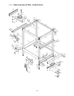
Страница 18: ...18 11 2 1 Stand Assembly 737004 Exploded View ...

Страница 19: ... Machine Screw M4 0 7 20 2 30 TS 2311061 Hex Nut Full M6 1 0 1 31 TS 0640091 Nylon Lock Hex Nut 3 8 16 1 32 TS 1550071 Flat Washer M10 1 34 SBR30M 53 Hex Cap Screw M8 90 2 35 5AD D04A Phillips Pan Hd Machine Screw M5 0 8 8 6 36 JRL912 236 Support Plate 1 37 JRL912 237 Phillips Pan Hd Machine Screw M5 0 8 45 4 38 JRL912 238 Tool Bracket 1 39 TS 1550061 Flat Washer M8 2 40 TS 1550031 Flat Washer M5 ...

Страница 20: ...20 11 3 1 Dust Collection Box Assembly 737005 Exploded View 5N 14N 3 3 2N 8 4 12 11 12 10 7 13 4 19 20 20 4 3 3 3 15 16 17 1N 6N 9N 18 3 3 ...

Страница 21: ...inuous Hinge 1 6N JRL912 306N Left Panel 1 7 JRL912 307 Rear Panel 1 8 JRL912 308 Power Cord Clamp 2pcs 2 9N JRL912 309N Bottom Panel 1 10 JRL912 310 Adjustable Vent Base 1 11 JRL912 311 Adjustable Vent Plate 1 12 JRL912 312 Rivet M32 5 13 JRL912 313 Dust Hose M63 80cm 1 14N JRL912 314N Door Panel 1 15 TS 1482021 Hex Cap Screw M6 1 0 12 6 16 TS 2361061 Lock Washer M6 6 17 TS 1550041 Flat Washer M6...

Страница 22: ...2 11 4 1 Fence Assembly 737001 Exploded View 9 9 25 23 26 28 10 11 4 12 13 14 15 16 18 17 19 20 22 5 6 5 6 21 21 4A 31 30 22 3 32A 8 8 12 13 18 16 17 19 15 14 1 2 4 5 6 5 6 5 6 2 4 4 5 5 7 7 32 24 27 29 ...

Страница 23: ...0mm 2 16 JRL912 416 Square Nut 1 4 6 17 TS 1550041 Flat Washer M6 6 18 TS 1503031 Socket Head Cap Screw M6 1 0 12 8 19 TS 0050021 Hex Cap Screw 1 4 20x5 8 6 20 JRL912 420 Lock Knob M6 12 2 32 JRL912 432 Dust Port 1 Optional Accessories 8 JRL912 408 Shims for Sub Fence set of 2 401mm 1 21 737010 Vertical Feather Board Assembly set of 2 1 22 737011 Horizontal Feather Board Assembly set of 2 1 32A 73...

Страница 24: ... TS 2311061 Hex Nut M6 1 0 10 4 TS 1503041 Socket Head Cap Screw M6 1 0x16 6 5 TS 2361061 Lock Washer M6 6 6 TS 1550041 Flat Washer M6 6 11 5 3 MDF Table Assembly 737003 Parts List Index No Part No Description Size Qty 1 JRL912 601 Router Table MDF 32 x24 1 2 JRLS 602 Phillips Flat Hd Wood Screw M7x40 10 4 JRLS 603 Pan Head Wood Screw 3 16 x 5 8 28 12 F010966 Socket Head Flat Screw BO not shown M6...

Страница 25: ...itional action needed JET has Authorized Service Centers located throughout the United States For the name of an Authorized Service Center in your area call 1 800 274 6846 or use the Service Center Locator on the JET website More Information JET is constantly adding new products For complete up to date product information check with your local distributor or visit the JET website How State Law App...

Страница 26: ...26 This page intentionally left blank ...

Страница 27: ...27 This page intentionally left blank ...

Страница 28: ...28 427 New Sanford Road LaVergne Tennessee 37086 Phone 800 274 6848 www jettools com ...

Отзывы: