11
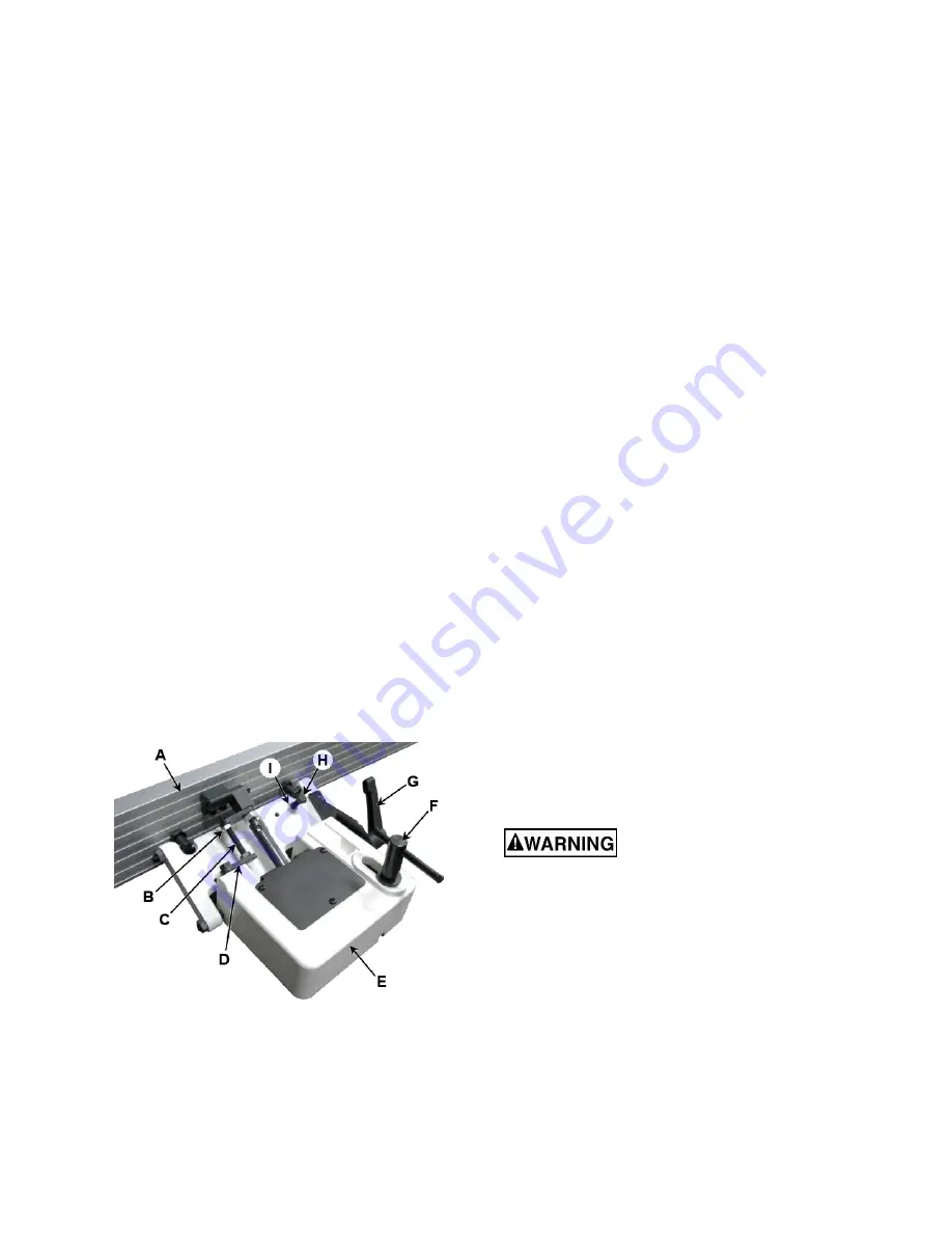
5. If the
fence
(A) is not square to the table,
release the
tilt locking handle
(G), loosen the
lock nut
(B), and turn the
stop bolt
(C) until
the fence is square to the table.
6. Tighten the
lock nut
(B) to retain the setting.
Tighten the
tilt locking handle
(G).
45° Backward Stop Fence Adjustment
The 45º fence backward stop (fence positioned
away from the operator) is controlled by the
backward stop bolt
(H).
1. Set the
infeed table
(F, Fig. 7) to approx-
imately the
same height as the
outfeed table
(A, Fig. 7).
2. Move the
fence
(A) by releasing the
assembly locking handle
(F) and pushing the
fence assembly
(E) until it overlaps the
tables, then tighten the
assembly locking
handle
(F).
3. Adjust the
fence
(A) to a 135° angle by
releasing the
tilt locking handle
(G), moving
the
stop plate
(D) out of the way, and
positioning the fence against the
backward
stop bolt
(H). Tighten the
tilt locking handle
(G).
4. Place an angle measuring device on the table
and against the
fence
(A) to confirm a 135º
setting.
5. To adjust, loosen the
tilt locking handle
(G)
and
lock nut
(I), then turn the
backward stop
bolt
(H) until a 135º angle is obtained.
6. Tighten the
lock nut
(I) to retain the setting.
Tighten the
tilt locking handle
(G).
Figure 9
10.2
Table and Knife Adjustments
For accurate jointing, at least three things must
be true:
1. Infeed and outfeed tables must be coplanar.
2. Knives or knife inserts must be set in the
cutterhead so that the highest point of their
arc is level with the outfeed table.
3. On the standard cutterhead, knives must be
parallel with the outfeed table across the
entire length of the knives.
These alignments are explained below.
10.3
Coplanar Alignment
Definition of Coplanar
When the infeed table is set to the same level as
the outfeed table and all points on the tables lie in
the same plane, thus forming a
“perfect” flat
surface, the tables are said to be coplanar.
For optimum performance of the jointer, the
infeed and outfeed tables must be coplanar. If
they are not, the finished workpiece may have a
slight taper or twist across its jointed width or
length.
Determining If Tables Are Coplanar
Refer to Figures 10 and 11:
The tables have been set coplanar at the factory,
but they should be double-checked by the
operator. Also, as the machine undergoes use,
the tables should be checked occasionally and
adjusted if necessary.
The procedure described below uses a steel
straight edge to set the tables, which should be
accurate enough for most purposes.
Important:
The tables must be locked in position
when performing the following test.
Disconnect machine from
power
source
before
making
any
adjustments. Failure to comply may cause
serious injury.
1. Disconnect machine from power source.
2. Fully swing the
cutterhead guard
(G) away
from the
fence
(B). It is recommended to then
use a
6mm hex wrench
(F) (one is included
with the machine) as a makeshift stop to hold
the guard in place. To do this, insert the
wrench into the front right roller tension
adjustment screw. The cutterhead guard can
then be released and the wrench will prevent
it from swinging back towards the fence.
Содержание JPJ-12B
Страница 28: ...28 15 1 Infeed Table Assembly Exploded View ...
Страница 30: ...30 15 3 Outfeed Table Assembly Exploded View ...
Страница 32: ...32 15 5 Cutterhead Assembly Exploded View ...
Страница 34: ...34 15 7 Planer Table Assembly Exploded View ...
Страница 36: ...36 15 9 Blade Guard Assembly Exploded View ...
Страница 38: ...38 15 11 Gearbox Assembly Exploded View ...
Страница 40: ...40 15 13 Cabinet Assembly Exploded View ...
Страница 43: ...43 15 15 Fence Assembly Exploded View ...
Страница 45: ...45 16 0 Electrical Connections for JPJ 12B JPJ 12BHH ...
Страница 47: ...47 ...
Страница 48: ...48 427 New Sanford Road La Vergne Tennessee 37086 Phone 800 274 6848 www jettools com ...


