Jet J-FK350-4 Скачать руководство пользователя страница 2

 IMPORTANT SAFETY INSTRUCTIONS 

1.

Read and understand the entire owner's
manual before attempting assembly or
operation.

2.

Read and understand the warnings posted on
the machine and in this manual. Failure to
comply with all of these warnings may cause
serious injury.

3.

Replace the warning labels if they become
obscured or removed.

4.

The cold saw is designed and intended for use
by properly trained and experienced personnel
only. If you are not familiar with the proper and
safe operation of a cold saw, do not use until
proper training and knowledge have been
obtained.

5.

Do not use this cold saw for other than its
intended use. If used for other purposes, JET
disclaims any real or implied warranty and
holds itself harmless from any injury that may
result from that use.

6.

Always wear approved safety glasses/face
shields while using this cold saw. Everyday
eyeglasses only have impact resistant lenses;
they are not safety glasses.

7.

Before operating the cold saw, remove tie,
rings, watches and other jewelry, and roll
sleeves up past the elbows. Remove all loose
clothing and confine long hair. Non-slip
footwear or anti-skid floor strips are
recommended. Do 

not

 wear gloves.

8.

Wear ear protectors (plugs or muffs) during
extended periods of operation.

9.

CALIFORNIA PROPOSITION 65 WARNING:
This product contains chemicals known to the
State of California to cause cancer, or birth
defects or other reproductive harm.

10. This product, when used for welding, cutting,

or working with metal, produces fumes, gases,
or dusts which contain chemicals known to the
State of California to cause birth defects and,
in some cases, cancer. (California Health and
Safety Code Section 25249.5 et seq.)

11. Do not operate this machine while tired or

under the influence of drugs, alcohol or any
medication.

12. Make certain the switch is in the 

OFF

 position

before connecting the machine to the power
supply.

13. 

Make certain the machine is properly
grounded.

14. Make all machine adjustments or maintenance

with the machine unplugged from the power
source.

15. Remove adjusting keys and wrenches. Form a

habit of checking to see that keys and
adjusting wrenches are removed from the
machine before turning it on.

16. Keep safety guards in place at all times when

the machine is in use. If removed for
maintenance purposes, use extreme caution
and replace the guards immediately.

17. Make sure the cold saw is firmly placed on a

secure foundation.

18. Check damaged parts. Before further use of

the machine, a guard or other part that is
damaged should be carefully checked to
determine that it will operate properly and
perform its intended function. Check for
alignment of moving parts, binding of moving
parts, breakage of parts, mounting and any
other conditions that may affect its operation.
A guard or other part that is damaged should
be properly repaired or replaced.

19. Provide for adequate space surrounding work

area and non-glare, overhead lighting.

20. Keep the floor around the machine clean and

free of scrap material, oil and grease.

21. Keep visitors a safe distance from the work

area. 

Keep children away.

22. Make your workshop child proof with padlocks,

master switches or by removing starter keys.

23. Give your work undivided attention. Looking

around, carrying on a conversation and “horse-
play” are careless acts that can result in
serious injury.

24. Maintain a balanced stance at all times so that

you do not fall into the blade or other moving
parts. Do not overreach or use excessive force
to perform any machine operation.

25. Use the right tool at the correct speed and

feed rate. Do not force a tool or attachment to
do a job for which it was not designed. The
right tool will do the job better and safer.

26. 

Use recommended accessories; improper
accessories may be hazardous.

27. Maintain tools with care. Keep saw blades

sharp and clean for the best and safest
performance. Follow instructions for lubricating
and changing accessories.

Содержание J-FK350-4

Страница 1: ...Operating Instructions and Parts Manual Ferrous Manual Cold Saws Models J FK350 2 J FK350 4...

Страница 2: ...chine to the power supply 13 Make certain the machine is properly grounded 14 Make all machine adjustments or maintenance with the machine unplugged from the power source 15 Remove adjusting keys and...

Страница 3: ...ngs and accessory equipment deemed necessary for any reason whatsoever About this machine and manual The J FK350 Cold Saw is designed to provide a reliable solution to the needs of machine shops and p...

Страница 4: ...peed Blade Speed RPM 44 and 88 44 and 88 Motor Motor 2HP 3PH 60Hz 2HP 3PH 60Hz Voltage 220VAC 440VAC Other Maximum Vise Opening 6 6 Coolant Capacity 3 gal 3 gal Dimensions 50 L x 28 W x 60 H 50 L x 28...

Страница 5: ...system To operate the machine the Power switch must be set to on and the High Stop Low switch must be set for Hi or Low Then press the trigger handle to start 7 5 Trigger Handle The trigger handle Fi...

Страница 6: ...t 440V These machines not supplied with a plug Use a plug and outlet rated at least 20amps The circuit for the machine should also be protected by at least a 20 amp circuit breaker or fuse Make sure t...

Страница 7: ...can be used for quickly making multiple cuts of the same length 11 2 Miter Adjustment To adjust the miter position follow the steps below while referring to Figure 10 1 Move the miter position lock A...

Страница 8: ...Remove excess chips periodically from the tank Use the coolant level gauge to check the coolant level 12 4 Changing the Saw Blade The cold saw must not be connected to the power source when changing...

Страница 9: ...let capacity and press against the walls of the workpieces resulting in poor cutting same situation with soft materials greater shearing stress and hence breakage of the blade Table 1 A larger pitch s...

Страница 10: ...tooth tooth pitch T 13 7 Teeth Shape C TYPE SHARPENING HZ Coarse toothing with roughing tooth raked on both sides and non raked finishing tooth The roughing tooth is about 0 3 mm higher Coarse toothin...

Страница 11: ...ting hollow profiles This is because as a result of the high cutting speeds 3400 rpm even with non ferrous materials the tool strikes against the wall of the profile to be cut several times thus requi...

Страница 12: ...may be left in the cut check and remove before starting work again Work piece not clamped firmly in place Any movement of the work piece during cutting can cause broken teeth check the vise jaws and c...

Страница 13: ...are present in input and output that it is not causing short circuits and responds when the reset coil is closed If it has tripped to protect the motor check the amperage setting reset and check the...

Страница 14: ...29 FK350 229 Retainer Nut 1 30 FK350 230 Flat Key 8x7x42mm 1 31 FK350 231 Flat Key 8x7x27mm 1 32 FK350 232 O Ring 1 33 FK350 233 O Ring P8 1 34 FK350 234 Pin 5mm Dia x 28 2 35 TS 1540071 Hex Nut M10...

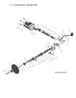
Страница 15: ...15 1 2 Head Assembly Exploded View...

Страница 16: ...Parts List Index No Part No Description Size Qty 1 FK350 501 Block 1 2 FK350 502 Shaft 1 3 FK350 503 Stop Rod 1 4 FK350 504 Scale Inch 1 6 FK350 506 Handle M8x30 2 7 FK350 505 Rivet 2 15 2 2 Stock St...

Страница 17: ...ay 440V 1 6 FK350 606 Lighted Selector Switch 1 7 TS 1502051 Socket Head Cap Screw M5x20 4 8 TS 1551031 Lock Washer M5 4 9 FK350 609 Cable Lock 3 10 J FK350 610 Rear Cover 1 11 TS 1503021 Socket Head...

Страница 18: ...g Bracket B 1 11 FK350 111A Return Spring 1 12 FK350 112 Chip Screen 1 13 TS 1505031 Socket Head Cap Screw M10x25 2 14 TS 1551071 Lock Washer M10 2 15 TS 1504041 Socket Head Cap Screw M8x20 2 16 TS 15...

Страница 19: ...15 4 2 Base Assembly Exploded View 7 23 2 14 16 24 8 10 15 13 11 9 12 22 21 17 3 19 6 20 4 5 18 1 FK 350 BASE ASS Y...

Страница 20: ...50 310 Filling Block 1 12 FK350 312 Cap 1 13 FK350 313 Setting Screw 1 14 FK350 314 Hex Nut M20x1 5P 1 15 J FK350 315 Cover 1 16 FK350 316 Tension Handle 1 17 FK350 317 Tension Nut 1 18 FK350 318 Pres...

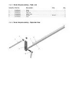
Страница 21: ...15 5 2 Manual Vise Assembly Exploded View...

Страница 22: ...1 10 FK350 410 Link Ring 1 11 FK350 411 Link Pin 1 12 FK350 412 Link Bracket 1 13 FK350 413 Link D 1 14 FK350 414 Link D Ring 1 15 TS 1504031 Socket Head Cap Screw M8x16 3 16 TS 1550061 Flat Washer M8...

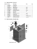
Страница 23: ...15 6 2 Guard Assembly Exploded View...

Страница 24: ...1 7 J FK350 707 Base B 1 8 TS 1491041 Hex Cap Screw M10x30 8 9 TS 1491061 Hex Cap Screw M10x40 2 10 TS 1491121 Hex Cap Screw M10x70 2 11 TS 2361101 Lock Washer M10 12 12 TS 1540071 Hex Nut M10 16 13 F...

Страница 25: ...cting Plate EA 7 TS 1502071 Socket Head Cap Screw M5x30 EA 8 FK350 808 Lock Block A EA 9 FK350 809 Lock Block B EA 10 FK350 818 Spring EA 11 FK350 811 Stopper EA 12 TS 1503051 Socket Head Cap Screw M6...

Страница 26: ...Wiring Diagram...

Отзывы: