11
7.9
Adjusting work stop
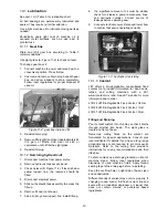
The work stop assembly (Figure 7-7) is used when
multiple pieces will be cut to identical length. Screw
the rod into the threaded hole on the front of fixed
jaw, and slide the stop onto the rod. Adjust to
desired positions, and tighten all handles and
knobs.
The stop can be rotated out of the way when not
used.
Figure 7-7: work stop
7.10
Limit switch adjustment
Limit switches have been correctly adjusted by the
manufacturer. If further adjustment is required,
proceed as follows.
7.10.1
Upper Limit Switch
The upper limit switch stops bow at highest position.
It has been correctly set by the manufacturer. If
future adjustment is needed, loosen knob and slide
rod (A, Figure 7-8). Retighten knob.
Figure 7-8: upper limit switch
7.10.2
Lower Limit Switch
The lower limit switch must be set so that blade
stops after workpiece has been cut through. It has
been properly set by the manufacturer. If adjustment
is needed, loosen jam nut and turn stop screw (B,
Figure 7-9) as required. Retighten jam nut.
Figure 7-9: lower limit switch
8.0
Operating controls
Refer to Figure 8-1.
Power Indicator Light (A)
– Illuminates whenever
machine is receiving electrical power.
Hydraulic motor (B)
– Press to start hydraulic flow.
Bow Up (C
1
)
– Press to raise bow. Bow will rise until
limit switch is activated.
This button is rendered
inactive in all modes while blade is engaged in
workpiece.
Bow Down (C
2
)
– Press to lower bow. Bow will
lower until limit switch is activated.
This button is
rendered inactive in all modes while blade is
engaged in workpiece.
Figure 8-1
Hydraulic Vise Close (D
1
)
– Press and hold to
clamp workpiece in vise, then release.
Hydraulic Vise Open (D
2
)
– Press and hold to
release workpiece in vise.
Manual/Auto Selector (E)
– Choose manual or
automatic bow movement. In manual mode, bow will
stop in lowered position after cut. In auto mode, bow
will return to raised position after cut.
Blade Start and Stop (F)
– Begins blade action and
starts cutting cycle.
Содержание HBS-1220DC
Страница 17: ...17 13 1 1 HBS 1220DC Base Assembly Exploded View ...
Страница 18: ...18 13 1 2 HBS 1220DC Bow Assembly Exploded View ...
Страница 25: ...25 13 2 1 HBS 1220DC Electrical Box Assembly Exploded View ...
Страница 27: ...27 14 0 Electrical Connections for HBS 1220DC Band Saw ...
Страница 29: ...29 15 0 Oil valve schematic ...
Страница 31: ...31 ...
Страница 32: ...32 427 New Sanford Road LaVergne Tennessee 37086 Phone 800 274 6848 www jettools com ...


