15
EVTBS16V
6. The lock handle (K, Fig. 10) secures the clamp assembly
to the table T-slot.
7. Pulling the release handle (H, Fig. 10) unlocks the slide
bar, allowing the front plate to be moved to clamp or
unclamp the material. Pushing the release handle forward
presses the slide bar forward slightly, locking the slide
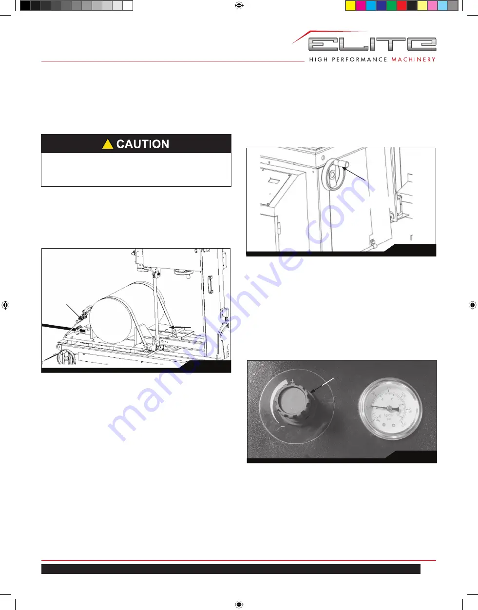
bar.
8. Figure 11 shows an optional clamping procedure to use
when working with large diameter pieces. Use the vise
plates to support and align the workpiece. Then use the
ratchet straps (L, Fig. 11) hooked on the edge of the
table to secure the workpiece and prevent unintended
movement.
10.5.2 Saw Head Movement - Automatic
1. The saw also can be fed forward automatically by
adjusting the feed force. Pull upward on the knob (N,
Fig. 13) and rotate clockwise
(CW)
or counterclockwise
(CCW)
until the desired feed is obtained.
2. Observe the chips to determine when the feed is
correct.
3. Press down on the adjustment knob to lock the setting.
Fig. 11
L
L
Fig. 12
M
10.5.3 Saw Head Movement - Travel Limits
1. The travel stops are generally used when cutting
multiple pieces to the same length.
2. The contact block (O, Fig. 14) contacts and actuates
the travel limit switches.
3. The retract travel stop (P, Fig. 14) is set at the factory
and is not normally adjusted.
4. The forward stop (Q, Fig. 14) should be adjusted about
1/8" - 1/4" past the point where the blade exits a cut.
Fig. 13
N
10.5 Feeding Stroke
Reference Figures 12, 13, and 14.
11.5.1 Saw Head Movement - Manual
The cutting head can be fed forward or backwards manually
by rotating the feed handle (M, Fig. 12) counterclockwise
(CCW)
or clockwise
(CW)
, respectively.
!
The lock handle (K) must be tight and the workpiece
clamped with the release handle (H) locked during
any cutting to prevent unintended movement.
891200_EVTBS16V Tilting Band Saw_Edition 1.indd 15
891200_EVTBS16V Tilting Band Saw_Edition 1.indd 15
5/10/22 10:22 AM
5/10/22 10:22 AM


