14
Vertical Tilting Band Saw
10.2 Blade Tracking Adjustment
Typically, the blade should track with the back edge of
the blade maintaining an approximate 1/32" gap from the
flange on the back of blade wheels.
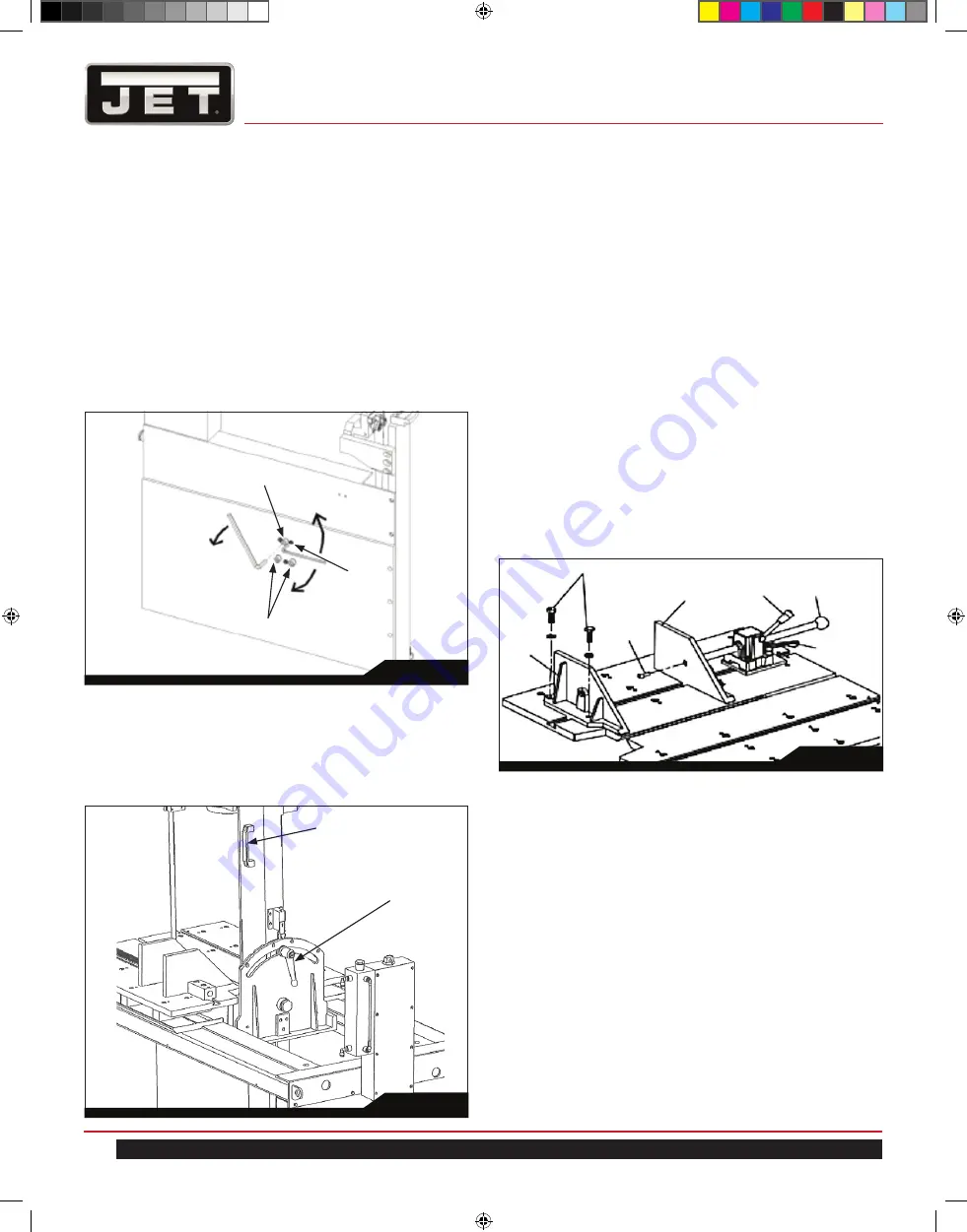
1. Loosen the three (3) hex head mounting bolts (A, Fig. 8)
on the back side of the lower wheel housing 1 to 1-1/2
turns.
2. Adjust the set screw (B, Fig. 8) to change the tracking of
the blade.
3. When the tracking is correct, evenly tighten the three (3)
hex head screws.
4. Check the tracking again.
10.3 Head Tilt Adjustment
1. The cutting head is adjustable to make angled cuts from
-45° to +45°. Be sure the upper blade guide will clear
any obstructions on the table before adjusting the cutting
head angle.
2. To adjust the cutting head angle, turn the lock handle
counterclockwise (CCW) (C, Fig. 9).
3. Holding the cutting head handle, tilt the head to desired
angle (D, Fig. 9).
4. When the desired angle is obtained, turn the lock handle
clockwise
(CW)
to secure the cutting head for operation.
10.4 Vise Plate Positioning
Reference Figures 10 and 11.
The vise system consists of two (2) interchangeable vise
plates and a quick clamp. One vise plate is mounted as the
stationary (rear) vise plate (E) and the other is mounted as the
movable (front) vise plate (F). The quick clamp is mounted in
the T-slot inline with and attached to the front vise plate.
The vise plates may be mounted on either side of the blade
and with either the square or angled edge toward the blade.
The quick clamp is moved to align with the plate which is
being used as the movable (front) plate.
The following gives only one example of how the vise plates
can be mounted to the saw table.
Fig. 8
Fig. 9
1. Place the rear vise plate in the T-slot and at a position on
the table so that the hold down bolts (I) are aligned with
the threaded mounting holes in the tabletop.
2. Use a hex key to secure the rear vise plate to the tabletop
with the hold down bolts (I).
3. Place the front vice plate in the T-slot, opposite the rear vise
plate. This will be vise plate flat surface to flat surface.
4. Place the quick clamp assembly into the T-slot aligned with
the front vise plate with the flat threaded end against the
vise plate and the ball knob (G) outward for the operator.
This assembly may be positioned as needed to allow for
clamping and releasing the vise plate.
5. Insert the M8 x25 socket head screw (J) through the plate
and into the slide bar for the quick clamp.
Fig. 10
A
B
A
D
C
E
J
K
G
I
F
H
891200_EVTBS16V Tilting Band Saw_Edition 1.indd 14
891200_EVTBS16V Tilting Band Saw_Edition 1.indd 14
5/10/22 10:22 AM
5/10/22 10:22 AM


