

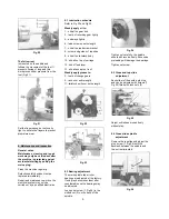


6
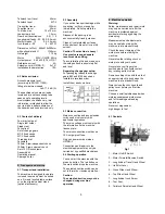
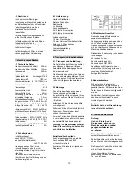
10…Tailstock Spindle Clamping
Lever
11…Tailstock Locking Screw
12…Tailstock Off-Set Adjustment
13…Automatic Feed Lever
14…Change Gear Box Lever
15…Reversing Gear Lever
16…V-Belt Tension Lever
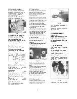
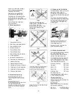
6.2 Chucking
Never exceed the max speed
limitation of the work holding device.
Jaw teeth and scroll must always be
fully engaged. Otherwise chuck jaws
may break and fly off in rotation (Fig
2).
Fig 2
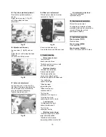
Avoid long workpiece extensions.
Parts may bend (Fig 3) or fly off (Fig
4).
Use tailstock or rests to support.
Fig 3
Fig 4
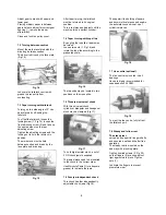
Avoid short clamping contact (A, Fig
5) or clamping on a minor part
diameter (B).
Fig 5
Face locate the workpiece for added
support.
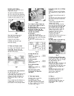
6.3 Tool setup
The cutting angle is correct when the
cutting edge is in line with the centre
axis of the work piece. Use the point
of the tailstock centre as a gauge
and shims under the tool to obtain
the correct centre height (Fig 6).
Fig 6
Use a minimum of two clamping
screws when installing the cutting
tool to the four way tool post.
Avoid big tool extensions.
6.4 Spindle speeds selection
The correct spindle speed depends
on the type of machining, the cutting
diameter, the material to be
machined and the cutting tool.
These are recommended max.
speeds for a 10mm cutting diameter
with HSS (high speed steel) tools:
Aluminium, brass
1500 RPM
Cast iron
1000 RPM
Mild steel
800 RPM
High carbon steel
600 RPM
Stainless steel
300 RPM
If carbide tools (HM) are used about
5 times higher speeds can be
chosen.
Generally speaking, the larger in
relation the cutting diameter, the
smaller the possible RPM.
For example:
Turning mild steel at a diameter of
20mm allows a speed of
400 RPM max.
with HSS tool
2000 RPM max.
with carbide tool
To change the spindle speed:
Unplug the machine from the power
source.
Loosen the locking screw on the
pulley cover, then open the cover.
Loosen the belt tension by lifting the
lever (A, Fig 7).
Fig 7
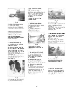
Change the belt location according
to the speed chart and the speed
you desire.
Tension the belt.
Close and lock the pulley cover.
6.5 Manual turning
Apron travel, cross travel and top
slide travel can be operated for
longitudinal and cross feeding (Fig
8).
Fig 8


