8
1700 Series Lathe
6.0 GENERAL INSTRUCTION
6.1 GENERAL LAYOUT OF LATHE
1. Headstock
2. Spindle
3. Bed
4. 4-Way tool post
5. Top slide
6. Saddle and Cross slide
7. Splash guard
8. Tailstock
9. One piece solid stand
10. Leadscrew
11. Feed shaft
12. Apron
13. Footbrake
14. Gearbox
15. End cover (Gear train)
Fig. 1
15
1
2
3
4
5
6
7
8
14
9
13
12
11
10
9
Содержание 892100
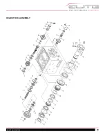
Страница 21: ...21 EGH1740 EGH1760 HEADSTOCK ASSEMBLY ...
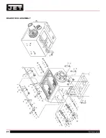
Страница 22: ...22 1700 Series Lathe HEADSTOCK ASSEMBLY ...
Страница 23: ...23 EGH1740 EGH1760 HEADSTOCK ASSEMBLY ...
Страница 24: ...24 1700 Series Lathe HEADSTOCK ASSEMBLY ...
Страница 28: ...28 1700 Series Lathe GEARBOX ASSEMBLY ...
Страница 29: ...29 EGH1740 EGH1760 GEARBOX ASSEMBLY ...
Страница 33: ...33 EGH1740 EGH1760 APRON L H ASSEMBLY ...
Страница 34: ...34 1700 Series Lathe APRON L H ASSEMBLY ...
Страница 39: ...39 EGH1740 EGH1760 4 WAY TOOL POST ...
Страница 41: ...41 EGH1740 EGH1760 SADDLES ASSEMBLY ...
Страница 42: ...42 1700 Series Lathe SADDLES ASSEMBLY 2 ...
Страница 45: ...45 EGH1740 EGH1760 BED AND SHAFTS ASSEMBLY ...
Страница 48: ...48 1700 Series Lathe END GEAR ASSEMBLY ...
Страница 50: ...50 1700 Series Lathe MAIN MOTOR ASSEMBLY ...
Страница 52: ...52 1700 Series Lathe CABINET AND PANEL ASSEMBLY FRONT MOVEABLE CHIP TRAY OPTIONS ...
Страница 56: ...56 1700 Series Lathe CONVENTIONAL TAILSTOCK ASSEMBLY ...
Страница 58: ...58 1700 Series Lathe STEADY REST ASSEMBLY ...
Страница 62: ...62 1700 Series Lathe 892156 5C COLLET CLOSER OPTIONAL ...
Страница 64: ...64 1700 Series Lathe 892157 TAPER ATTACHMENT OPTIONAL ...
Страница 68: ...68 1700 Series Lathe 12 0 WIRING DIAGRAM ...


