


14
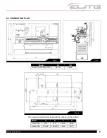
1700 Series Lathe
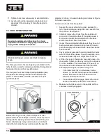
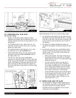
Fig. 11
Oil can be added or drained via hex drain plug located in
the bottom plate of the apron.
In addition to the one shot lubrication, oiler points are
provided for the saddle cross-slide and cross-slide nut.
Use a standard oil can with light machine oil or way
lubricant.
On the tailstock and tail end of leadscrew, lubrication
points are provided for daily attention from a standard oil
can.
It is recommended that all slideways, the leadscrew and
feed shaft are cleaned daily and then lightly lubricated.
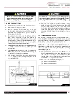
7.5 COMPLETING INSTALLATION
13. Exposed metal surfaces have been coated with a
rust protectant. Remove this using a soft rag and
mild commercial solvent or kerosene. Do not use
paint thinner, gasoline, or lacquer thinner, as these
will damage painted surfaces. Cover all cleaned sur-
faces with a light film of SAE-20W machine oil, such
as Mobil DTE Oil Heavy Medium.
14. Open the end gear cover. Clean all components
of the end gear assembly and coat all gears with
a heavy, non-slinging grease. Close the end gear
cover. (Note: A limit switch prevents the lathe from
operating when the end gear cover is open.)
7.6 BREAK-IN PERIOD
Do not run the lathe above 560 RPM for the first six hours
of operation, to allow gears and bearings to adapt and run
smoothly.
Push during working
A
Fill oil to level
8.0 ELECTRICAL CONNECTIONS
Electrical connections must be made by a qual-
ified electrician in compliance with all relevant
codes. This machine must be properly grounded
while in use to help protect the operator from elec-
trical shock and possible fatal injury.
Confirm that power available at the lathe’s location is the
same rating as the lathe.
IMPORTANT: The lathe must be wired properly
and phased correctly. The spindle should rotate
counterclockwise (as viewed from the tailstock
end) while the feed rod rotates clockwise (as
viewed from the tailstock end). If the phasing
needs correction, disconnect lathe from power
source and switch any two of the three power
leads (not the green ground wire).
Make sure the lathe is properly grounded.
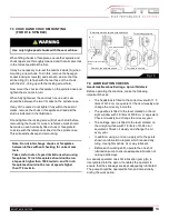
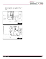
9.0 OPERATION
9.1 LATHE CONTROLS
A. Headstock selector
B. Electrical control
C. Gearbox (threads and feeds)
D. Apron control units, for surfacing, sliding and
Fig. 12
Main Switch
Содержание 892100
Страница 21: ...21 EGH1740 EGH1760 HEADSTOCK ASSEMBLY ...
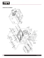
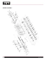
Страница 22: ...22 1700 Series Lathe HEADSTOCK ASSEMBLY ...
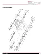
Страница 23: ...23 EGH1740 EGH1760 HEADSTOCK ASSEMBLY ...
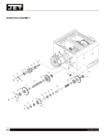
Страница 24: ...24 1700 Series Lathe HEADSTOCK ASSEMBLY ...
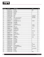
Страница 28: ...28 1700 Series Lathe GEARBOX ASSEMBLY ...
Страница 29: ...29 EGH1740 EGH1760 GEARBOX ASSEMBLY ...
Страница 33: ...33 EGH1740 EGH1760 APRON L H ASSEMBLY ...
Страница 34: ...34 1700 Series Lathe APRON L H ASSEMBLY ...
Страница 39: ...39 EGH1740 EGH1760 4 WAY TOOL POST ...
Страница 41: ...41 EGH1740 EGH1760 SADDLES ASSEMBLY ...
Страница 42: ...42 1700 Series Lathe SADDLES ASSEMBLY 2 ...
Страница 45: ...45 EGH1740 EGH1760 BED AND SHAFTS ASSEMBLY ...
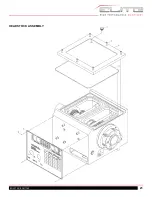
Страница 48: ...48 1700 Series Lathe END GEAR ASSEMBLY ...
Страница 50: ...50 1700 Series Lathe MAIN MOTOR ASSEMBLY ...
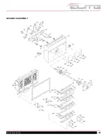
Страница 52: ...52 1700 Series Lathe CABINET AND PANEL ASSEMBLY FRONT MOVEABLE CHIP TRAY OPTIONS ...
Страница 56: ...56 1700 Series Lathe CONVENTIONAL TAILSTOCK ASSEMBLY ...
Страница 58: ...58 1700 Series Lathe STEADY REST ASSEMBLY ...
Страница 62: ...62 1700 Series Lathe 892156 5C COLLET CLOSER OPTIONAL ...
Страница 64: ...64 1700 Series Lathe 892157 TAPER ATTACHMENT OPTIONAL ...
Страница 68: ...68 1700 Series Lathe 12 0 WIRING DIAGRAM ...


