


17
EGH1740 | EGH1760
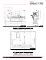
Fig. 18
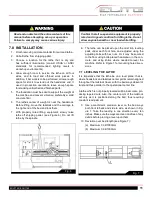
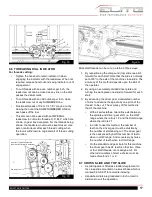
9.6 THREADING DIAL INDICATOR
For threads cutting:
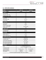
• Tighten the handnut to retain indicator in when
engaging the indicator with the leadscrew. When not
required, release hand-nut and swing indicator out of
engagement.
•
To cut threads with an even number per inch, the
leadscrew nut can be closed as any line on the dial
passes the datum mark.
• To cut threads with an odd number per inch, close
the leadscrew nut at any NUMBERED line.
• Fractional threads of 1/2 or 1/4 T.P.I. may be cut by
closing the nut at the SAME NUMBERED LINE on
each pass of the tool.
• This dial can not be used with an IMPERIAL
leadscrew to cut metric threads, D.P., M.P. which are
shown on gear box data plate. For the threads being
shown, the leadscrew nut must be kept closed. Use
apron control lever after each thread cutting when
the tool is withdrawn to original start of thread cutting
operation.
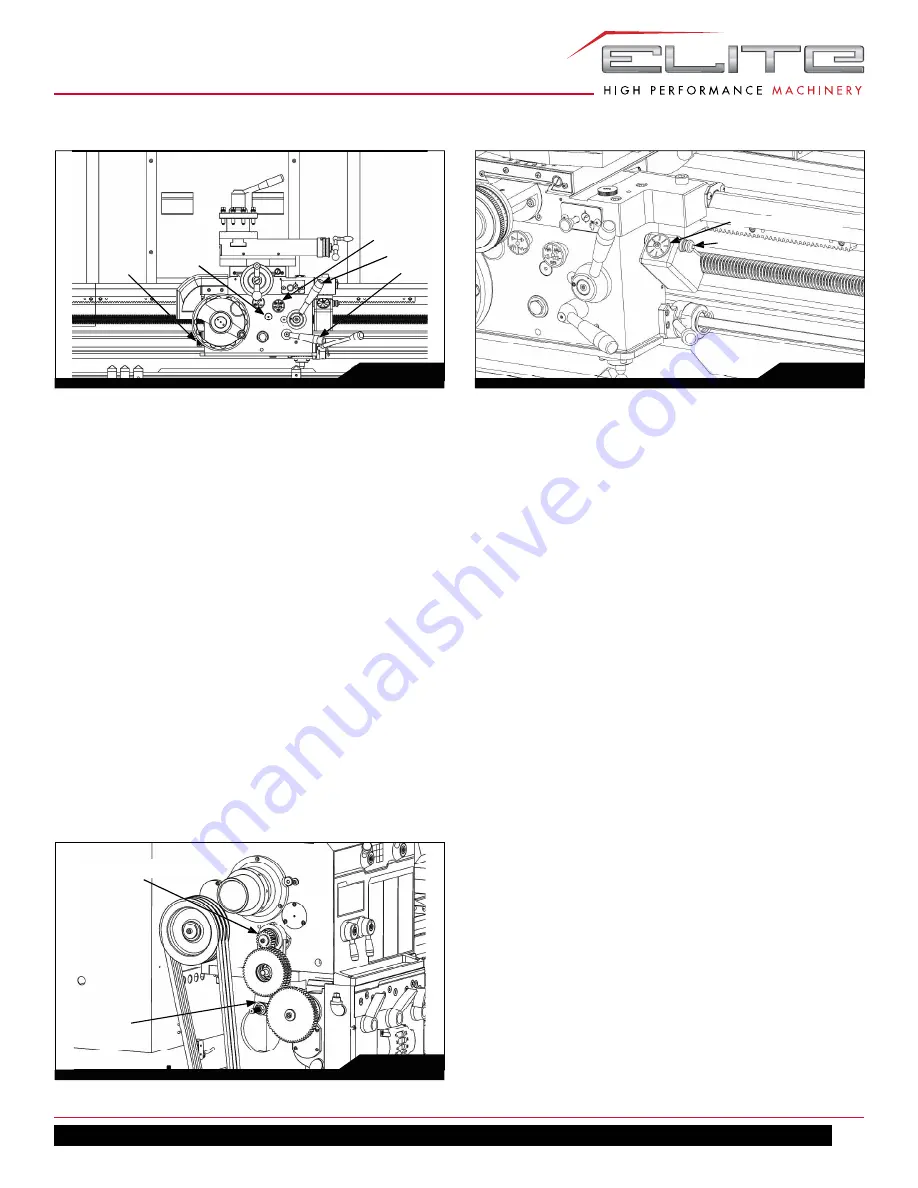
Fig. 19
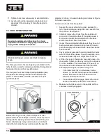
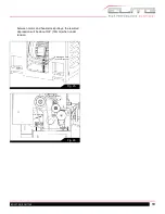
Multi-start threads can be cut on a lathe in three ways:
1. By repositioning the compound (top) slide one pitch
forward for each start. Note that the slide is normally
set at 90º to the axis of the machine cross-slide. The
accuracy of this method depends upon the skill of
the operator.
2. By using an accurately divided driver plate and
turning the work-piece one division forward for each
start.
3. By advancing the driver gear a calculated number
of turns to advance the spindle by one pitch of the
thread to be cut. The accuracy of this method is
that of the machine.
• With all series lathes, two ratios exist between
the spindle and driver gear shift, i.e. the LOW
range where the ratio is 1:2 and the HIGH range
where the ratio is 2:1
• In order to use this method, the number of
teeth on the driver gear must be divisible by
the number of starts being cut. The driver gear
is then advanced by half this number of teeth
when in LOW range. And conversely, by twice
the number of teeth when in HIGH range.
• On the standard end gear train for this machine
the driver gear has 24 teeth; so that two, three
or four start threads, can readily be cut. For
other odd numbers of start a choice must be
made of methods 1 or 2.
9.7 CROSS SLIDE AND TOP SLIDE
•
A solid topslide is fitted as standard equipment to
the cross-slide mounted on a swivel base which is
marked 0-90-0-90º for accurate indexing.
•
Handwheel dials are graduated in inch or metric
divisions to suit the operation.
A
D
C
Fig. 20
Handnut
Threading dial indicator
F
Gear 24T for Imperial leadscrew
(Gear 28T/22T for Metric leadscrew)
End Gear Train
Содержание 892100
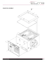
Страница 21: ...21 EGH1740 EGH1760 HEADSTOCK ASSEMBLY ...
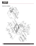
Страница 22: ...22 1700 Series Lathe HEADSTOCK ASSEMBLY ...
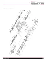
Страница 23: ...23 EGH1740 EGH1760 HEADSTOCK ASSEMBLY ...
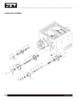
Страница 24: ...24 1700 Series Lathe HEADSTOCK ASSEMBLY ...
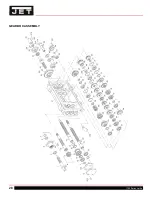
Страница 28: ...28 1700 Series Lathe GEARBOX ASSEMBLY ...
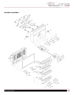
Страница 29: ...29 EGH1740 EGH1760 GEARBOX ASSEMBLY ...
Страница 33: ...33 EGH1740 EGH1760 APRON L H ASSEMBLY ...
Страница 34: ...34 1700 Series Lathe APRON L H ASSEMBLY ...
Страница 39: ...39 EGH1740 EGH1760 4 WAY TOOL POST ...
Страница 41: ...41 EGH1740 EGH1760 SADDLES ASSEMBLY ...
Страница 42: ...42 1700 Series Lathe SADDLES ASSEMBLY 2 ...
Страница 45: ...45 EGH1740 EGH1760 BED AND SHAFTS ASSEMBLY ...
Страница 48: ...48 1700 Series Lathe END GEAR ASSEMBLY ...
Страница 50: ...50 1700 Series Lathe MAIN MOTOR ASSEMBLY ...
Страница 52: ...52 1700 Series Lathe CABINET AND PANEL ASSEMBLY FRONT MOVEABLE CHIP TRAY OPTIONS ...
Страница 56: ...56 1700 Series Lathe CONVENTIONAL TAILSTOCK ASSEMBLY ...
Страница 58: ...58 1700 Series Lathe STEADY REST ASSEMBLY ...
Страница 62: ...62 1700 Series Lathe 892156 5C COLLET CLOSER OPTIONAL ...
Страница 64: ...64 1700 Series Lathe 892157 TAPER ATTACHMENT OPTIONAL ...
Страница 68: ...68 1700 Series Lathe 12 0 WIRING DIAGRAM ...


