The RPM Readout shows the spindle
speed
Use the toggle switch (B) to reverse
the spindle direction.
The headstock lock handle locks the
headstock in position. Unlock handle to
position the head along the lathe bed.
6. Machine operation
6.1 Correct operating position
Always support the tool on the tool rest
and guide with the palm of your hand
keeping your fingers closed.
(see Fig. 15 )
Fig 15
6.2 Tool selection
Successful wood turning does not
result from high speeds, but rather,
from the correct use of turning tools.
A perfect and sharp wood turner tool is
a precondition for professional wood-
turning.
Major tools:
Fig 16
Gouge (A, Fig 16)
, used for rapidly cut
raw wood into round stock, for turning
bowls and plates, for turning beds,
coves and other detail (Fig 17).
Fig 17
Scraper (B, Fig 16)
, used for diameter
scraping and to reduce ridges.
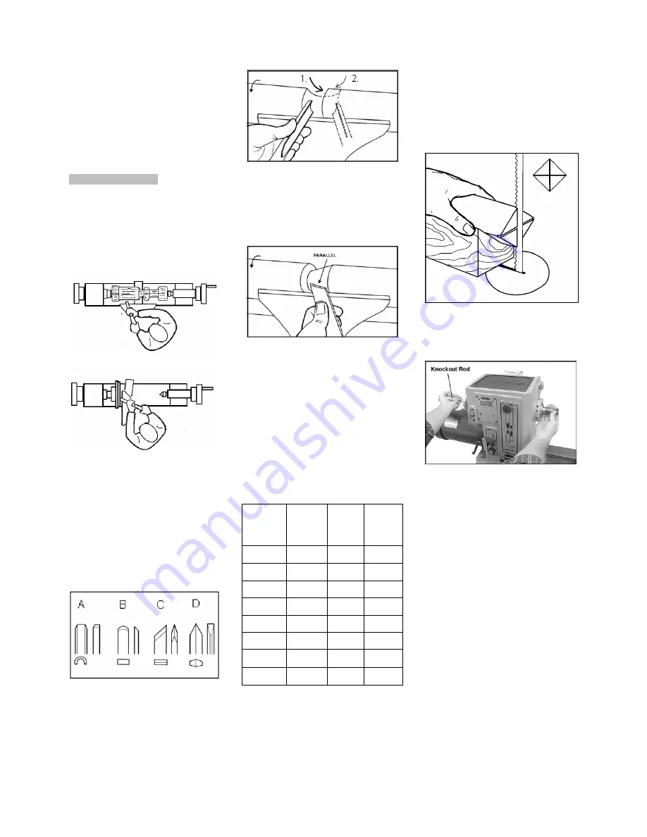
Skew Chisel (C, Fig 16),
used to
make vees, beads, etc. (Fig 18). The
bevel of scew is parallel to the cut.
Fig 18
Parting tool (D, Fig 16),
used to cut
directly into the material, or to make a
cut off. Also used for scraping and to
set diameters.
6.3 Speed selection:
Use low speeds for roughing and for
large diameter work. If vibrations
occur, stop the machine and correct
the cause.
See speed recommendations.
Speed recommendations
Workpiec
e
Diameter
mm
Roughin
g
RPM
Genera
l
Cutting
RPM
Finishin
g
RPM
< 50
1500 3200 3200
50-100
700 1600 2500
100-150
500 1100 1600
150-200
370 800 1200
200-250
300 650 1000
250-300
250 500 800
300-350
220 450 700
350-400
180 400 600
6.4 Turning between centres
With a ruler locate and mark the centre
on each end.
Put a dimple in each end of the shock.
Extremely hard woods may require
kerfs cut into the spur drive end of
stock (see Fig 19).
Fig 19
The spur drive centre locks into the
cleaned spindle taper and can be
removed with the knockout rod (Fig 20)
Fig 20
Mount the centred workpiece between
the spur drive centre and the tailstock
mounted live centre
Turn the tailstock hand wheel until the
live centre well penetrates the
workpiece. Reverse the hand wheel by
one quarter turn and lock the tailstock
spindle.
Turn the workpiece by hand to see if it
rests securely between centres and
can be rotated freely.
For turning between centres the tool
rest is set appr. 3mm higher than
centre line (Fig 21 and 22).


