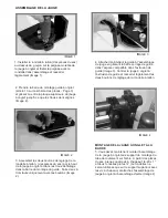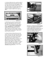
2. Take the Miter Fence Mounting Bar (Item
13 on the parts diagram - page 3) and slide
it in between the miter gauge top plate and
the gauge base plate until the 1/4” threaded
holes line up. (Fig. 2)
ASSEMBLING THE MITER GAUGE
3. Assemble the two brass fence
adjustment knobs (from the parts bag)
through the top of the Miter Gauge and into the
threaded holes in the fence mounting bar. Start
the knobs into the holes two to three turns only
(Fig. 2).
FIG. 1
1
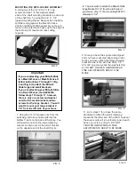
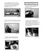
. Install the 1” brass washer (from the parts
bag) over the stud on the miter gauge
knurled handle and thread the handle with
the washer into the assembly and lightly
tighten (Fig. 1).
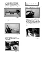
FIG. 3
4. Now attach the fence to the gauge
assembly by sliding the fence clamping bar
into the matching slot machined into the
fence extrusion (Fig. 3). Center the miter
gauge assembly to the fence extrusion and
lightly tighten the two brass fence
adjustment knobs.
FIG. 2
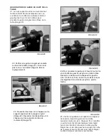
MOUNTING THE MITER GAUGE TO THE BAR
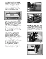
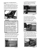
5. You must now mount the miter gauge
assembly to the bearing tube mounting
brackets on the shaft. From the parts bag
take four of the 1/4-
20 x 1” cap screws and two ¼”
flat washers (the washers will only be used on the
upright bracket with the cap screws) and attach
the miter gauge assembly to the shaft assembly
(Fig. 4).
FIG. 4
Содержание Mite R Slide
Страница 17: ......


