background image

User Manual

Model #06001

61 Forest Plain Road 

Oro-Medonte, Ontario, Canada 

L3V 0R4

Toll Free: 1-

866-272-7492

Local: 705-726-8233

Fax: 705-327-0295

Email: [email protected]


Website: www.jessem.com


Thank you for choosing this product from


JessEm Tool Company. We appreciate your


support and hope that our product serves you


well. This product is designed to provide


many years of reliable service provided it is


used as intended and taken care of.


This user manual will assist you in assembly


and general operation of this product. It is


not our intent to teach you about


woodworking. It is assumed that you are an


experienced woodworker with the basic skills


and experience necessary to use this product


safely. If after reading the following


instructions, if you are unsure or


uncomfortable about safely using this


product we urge you to seek additional


information through widely available


woodworking books or classes.


IMPORTANT!


Read and understand the contents of


this 

manual before assembly or


operation of 

this product.


As part of our Continuous Product


Improvement Policy, JessEm products are


always advancing in design and function.


Therefore there may be differences between


what is shown in our catalogs, website or at


retail display and what is sold at time of


purchase. We reserve the right to make


positive changes to our products at our


discretion.


Suggested Router Bit Speeds


Bit Diameter

1” 

(25mm)


1-

1/4” - 2” 

(30-50mm)


2-

1/4” - 2-1/2” (55-65mm)


3” - 3-1/2” 


(75-90mm)


Max. Speed

24,000 RPM
18,000 RPM
16,000 RPM
12,000 RPM

We do not recommend or support the


application of our Mite-R-Slide to other 
commercial or custom made fences and 
therefore will not commit to resolving any 
issues for applications other than our


Mast-R-

Fence models #04001, #04010 and Rout-R-
Fence Model # 04100.


Mite


R


Slide

The Mite-R-Slide is designed to fit the 

JessEm Mast-R-Fence, JessEm Mast-R-

Fence II or JessEm Rout-R-Fence only.

Содержание Mite R Slide

Страница 1: ...al information through widely available woodworking books or classes IMPORTANT Read and understand the contents of this manual before assembly or operation of this product As part of our Continuous Product Improvement Policy JessEm products are always advancing in design and function Therefore there may be differences between what is shown in our catalogs website or at retail display and what is s...

Страница 2: ...r and all knobs are tightened and secure before each use JESSEM TOOL LIMITED WARRANTY All JessEm products are warranted to be free from defects in material and workmanship JessEm will repair or replace any product which upon inspection proves to be defective for a period of 1 year from dated receipt and proof of purchase All warranty claims should be made direct to JessEm Tool Company Contact Jess...

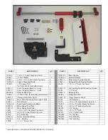
Страница 3: ...54 4 Phenolic Sub Fence 1 E0054 3 Bearing Tube 1 S0014 Hex T Nut for mounting accessories 2 S0018 1 Gauge Pivot Pin 1 S0013 1 Chrome Plated Steel Shaft 1 E0001 22 Gauge Indicator Block 1 S0005 4 Miter Fence Mounting Bar Long T Nut 1 F0008 20 Jam Nut 2 E0056 Mite R Fence 1 F0130 20 x 5 8 Socket Head Cap Screw 1 S0010 4 Fence Adjustment Knob Brass 2 F0014 20 x Socket Head Cap Screw 6 E0059 1 Miter G...

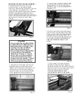
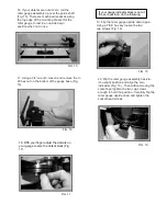
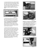
Страница 4: ...ge knurled handle and thread the handle with the washer into the assembly and lightly tighten Fig 1 FIG 3 4 Now attach the fence to the gauge assembly by sliding the fence clamping bar into the matching slot machined into the fence extrusion Fig 3 Center the miter gauge assembly to the fence extrusion and lightly tighten the two brass fence adjustment knobs FIG 2 MOUNTING THE MITER GAUGE TO THE BA...

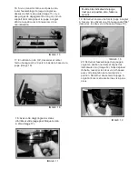
Страница 5: ...ng bracket to the fence with two of the 1 4 20 x 3 4 cap screws and two washers Fig 8 DO NOT TIGHTEN HARDWARE AS FINE ADJUSTMENTS NEED TO BE MADE 11 As in steps 7 thru 9 use the same hardware to attach the small clamping bracket at the other end of the shaft however the square nuts will run vertically one in each track of your fence Fig 9 DO NOT TIGHTEN HARDWARE AS FINE ADJUSTMENTS NEED TO BE MADE...

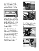
Страница 6: ...screws on the large fence clamping bracket Fig 11 Check the slide for a smooth action If not smooth slightly loosen all cap screws to release any possible torque in the shaft Re tighten cap screws and check for a smooth sliding action If necessary re check the shaft for parallel and repeat steps 11 thru 13 FIG 13 13 Make sure the miter gauge bracket is riding against the Mast R Fence If it is not ...

Страница 7: ...15 FIG 16 17 Using a 3 4 wrench loosen and remove the 20 hex nut on the bottom of the gauge base Fig 16 20 Flip the miter gauge assembly back to it s upright position and align the zero indicators Fig 19 Then without moving the scale finger tighten the two cap screws enough to hold the position Carefully flip the miter gauge upside down and tighten the socket head screws FIG 17 FIG 18 18 With your...

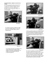
Страница 8: ...need to make the following adjustment 23 Loosen the two cap screws on the upright miter gauge bracket Fig 22 Now loosen the cap screws on both bearing tube brackets Fig 23 FIG 22 FIG 23 FIG 24 24 To tip the fence forward turn the far left set screw until it bottoms out Then loosen the left cap screw a turn Then turn the set screw clockwise again until it bottoms out SQUARING THE FENCE TO THE TABLE...

Страница 9: ...omprendre le contenu de ce manuel avant d assembler ou d utiliser ce produit Dans le cadre de notre politique continue d amélioration des produits JessEm fait toujours tout pour améliorer la conception et le fonctionnement de ses produits Par conséquent il peut y avoir quelques différences entre ce qui est indiqué dans nos catalogues site internet ou points de vente et au moment de votre achat Nou...

Страница 10: ... DE JESSEM TOOL Tous les produits JessEm sont garantis de tous défauts de main d œuvre et de matériels JessEm remplacera ou réparera n importe quel produit qui lors d une inspection sera considéré comme défectueux pendant une période d une 1 année à partir de la date d achat et cela avec une preuve d achat Toute réclamation de garantie devra être faite directement à la compagnie JessEm Tool Contac...

Страница 11: ... 1 E0054 3 Tube de roulement 1 S0014 Écrou hexagonal en forme de T Pour les accessoires de montage 2 S0018 1 Goupille de jauge 1 S0013 1 Arbre en acier plaqué en chrome 1 E0001 22 Bloc d indicateur de jauge 1 S0005 4 Barre de montage pour guide à onglet Écrou long en forme de T 1 F0008 Contre écrou 20 2 E0056 Mite R Fence 1 F0130 Vis à chapeau à tête creuse 20 x 5 8 1 S0010 4 Boulon de réglage à g...

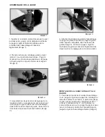
Страница 12: ...la poignée avec la rondelle dans l assemblage et resserrer légèrement Image 1 IMAGE 3 4 Attacher maintenant le guide à l assemblage de jauge en glissant la barre serrage de guide dans l espace compatible dans l extrusion de guide Image 3 Centrer la jauge à onglet à l extrusion de guide et resserrer légèrement les deux boulons de réglage de la rondelle à laiton FIG IMAGE 2 MONTAGE DE LA JAUGE À ONG...

Страница 13: ...que vous avez attachez le grand support au guide avec deux vis à chapeau 1 4 20 x 3 4 et deux rondelles Image 8 NE PAS SERRER LE MATÉRIEL CARE D AUTRES RÉGLAGES DOIVENT ÊTRE FAITS 11 Comme pour les étapes de 7 à 9 utilisez le même matériel pour attacher le petit support à l autre bout de l arbre Cependant les écrous à quatre pans seront au sens vertical Un de chaque côté de votre guide Image 9 SER...

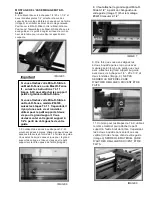
Страница 14: ...sition arrière et mettre quatre vis à chapeau sur le grand support de serrage du guide Image 11 Vérifier que tout est bien lisse Desserrer les vis si ce n est pas le cas Si nécessaire revérifier l arbre et répéter les étape de 11 à 13 IMAGE 13 13 S assurer que le support de jauge à onglet est contre le Mast R Fence Si ce n est pas le cas régler l assemblage de l arbre par l arrière ou l avant afin...

Страница 15: ...MAGE 15 IMAGE 16 17 En utilisant un clé 3 4 desserrer et retirer l écrou hexagonal 20 vers le bas de la base de la jauge Image 16 20 Retourner l assemblage de la jauge à onglet en position normale et aligner les indicateurs zéro Image 19 Sans déplacer l échelle resserrer les deux vis à chapeau avec votre doigt afin de la maintenir en position Retourner doucement la jauge à onglet à l envers et res...

Страница 16: ...Desserrer les deux vis à chapeau sur le support supérieur de la jauge à onglet Image 22 Desserrer maintenant les vis à chapeau sur les supports du tube de roulement Image 23 IMAGE 22 IMAGE 23 IMAGE 24 24 Pour renverser le guide vers l avant tourner la vis à l extrême gauche jusqu à ce qu elle tombe Desserrer ensuite la vis à chapeau de gauche d un 1 4 de tour Puis tourner la vis dans le sens des a...

Страница 17: ......

Отзывы: