background image


Page 68 

Operating Manual E4-2800/4200/5200 / M4-3000/4000/5500 

04/2014 


13.4    Energy value 


Display for:  

  Welding current [A] 

  Plate thickness [mm] 

  Wire feed speed [mmin] 

  Welding current  „Hold-value “ 


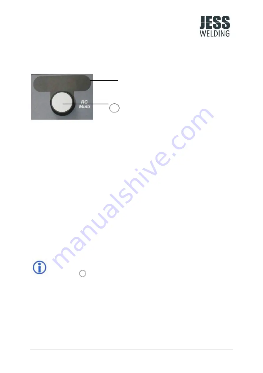
Rotary pushbutton for pre-set values: 

Rotational function: 


Selection of wire feed speed / energy 


Push function for changing display (press for 3 sec) 

  Welding current [A] 

  Plate thickness [mm] 

  Wire feed speed [m/min] 


By turning the rotary pushbutton (E) a wire feed speed / energy value can be selected as a 

default value. 


Alternatively, the expected welding current or plate thickness can be set as default value by 

pressing the pushbutton.  


If the function PowerPulse (PP) has been selected, the parameters of energy 1 can be 

adjusted:  

  Wire feed speed 

  Arc length correction 

  Time period of energy 1 in sec. (0,01 sec. steps / max. 2,50 sec.) 


If the function HC MAG has been activated (where HC MAG module and a valid 

characteristic are available), the following parameters can be adjusted:  

  Wire feed speed 

  Arc length correction / voltage set value 


At weld end, the current value achieved during welding is displayed (welding 

current „hold-value “). In order to display the pre-set values, press the rotary  

push-button       .


Содержание E4-2800 PULS RMT

Страница 1: ...Operating manual Inverter Welding Power Source for MIG MAG Processes E4 2800 4200 5200 PULS RMT M4 3000 4000 5500 RMT Cooling Unit K4 ...

Страница 2: ...d the mouse pointer changes Hyperlinks will change to a position in the document that provides further context information Change back to the original text position in the document via the Back button of your PDF viewer program Subject to technical and or optical changes Any kind of reproduction in whole or in part as well as processing or distribution using electronic systems requires the written...

Страница 3: ...it 15 5 4 Connection for Push Pull welding torch and for potentiometer control Option 16 6 OPERATING ELEMENTS FOR MACHINE CONTROL 17 6 1 Operating concept 17 6 2 Control panel version UNO Overview 18 6 3 Control panel details 19 6 4 Potentiometer control Option 32 7 COMMISSIONING 33 7 1 General Instructions 33 7 2 Utilisation for intended purposes only 33 7 3 Installation requirements 33 7 4 Mains...

Страница 4: ...uit diagram E4 2800 4200 5200 M4 3000 4000 5500 53 11 2 Legend to circuit diagram E4 2800 4200 5200 M4 3000 4000 5500 part 1 60 11 3 Circuit diagram cooling set K4 62 11 4 Legend to circuit diagram cooling set K4 63 12 SPARE PARTS LIST E4 2800 4200 5200 M4 3000 4000 5500 COOLING SET K4 64 13 Remote Control RC Multi 66 13 1 Technical data remote control RC Multi 66 13 2 Description front view 66 13...

Страница 5: ... better understanding and safe operation of the unit For sure you might discover one or the other new feature that helps you control your processes easier Please also observe the safety instructions in chapter 2 We wish you much pleasure with your new Jäckle Ess welding unit 1 2 Product description The MIG MAG pulse inverter welding power source E4 2800 is based on a new power supply with extremel...

Страница 6: ...nmental conditions The device must not be operated in hazardous areas The environment must be free from excessive dust unusual mechanical stresses vibrations shocks and aggressive media unless they occur during welding The device should be placed on a flat horizontal ground If it has to be placed on an inclined plane or on a higher working place machine and the gas bottle must be adequately secure...

Страница 7: ...hat fire extinguishing equipment appropriate to the welding process is available close to the welding area and that easy access is possible Explosion Never weld on or in the vicinity of containers which are under pressure and do not weld in rooms with a high concentration of explosive powders gases or vapours High pressure gas cylinders have to be handled with utmost care The gas cylinder must not...

Страница 8: ...se in the industrial sector In other areas an electromagnetic compatibility is not assured The user is responsible for the installation and operation of the welding machine according to the manufacturer s instructions If there is electromagnetic interference the operator is responsible for finding a solution with the technical assistance of the manufacturer of the welding machine In order to reduc...

Страница 9: ...n into account Earth connection of workpiece If the workpiece is not put to earth for reasons of electrical safety or because of its size and position e g shipbuilding a connection of the workpiece may reduce emissions in certain cases It must be ensured however that earthing of the workpiece does not increase the risk of accident to the user or causes damage to other electrical equipment In this ...

Страница 10: ...leaned with a cleaning drill after welding one wire coil 15 kg The liners must be cleaned after welding 50 100 kg wire depending on the wire size To do this they are pulled out of the outer hose Then outer hose and liners are blown out with dry and clean compressed air Daily Checks Check the machine for abnormal vibration humming noise and smell Check connecting sockets cables hoses and torch for ...

Страница 11: ... interval Depending of the degree of utilisation at least annually Cleaning X X Visual inspection X X Electrical test measurement of Open circuit voltage X X Insulation resistance X X Protective conductor resistance X X Primary leakage current Secondary leakage current Alternative to insulation resistance X Functional test X Test report label X X Tests have to be documented in a test report and a ...

Страница 12: ...ype of cooling AF Dimensions air cooled with rubber feet L x W x H 700 x 350 x 420 mm Dimensions air cooled with wheels undercarriage FW4 L x W x H 1000 x 500 x 620 mm Dimensions water cooled with rubber feet L x W x H 700 x 350 x 660 mm Dimensions water cooled with wheels undercarriage FW4 L x W x H 1000 x 500 x 860 mm Weight air cooled with rubber feet 45 kg Weight air cooled with wheels underca...

Страница 13: ...20 A 500 A 480 A Welding current at 100 ED 40 C MIG MAG MMA 310 A 280 A 450 A 420 A Type of protection IP 23 S IP 23 S Type of cooling AF AF Dimensions air cooled with rubber feet L x W x H 700 x 350 x 660 mm 700 x 350 x 660 mm Dimensions water cooled with wheels undercarriage FW4 L x W x H 1000 x 500 x 1100 mm 1000 x 500 x 1100 mm Weight air cooled with rubber feet 70 kg 82 kg Weight water cooled...

Страница 14: ...AC 400 V Nominal frequency 50 Hz Mains fuse protection 16 A Max cooling capacity 800 W Max pressure 4 0 bar Type of protection IP 23 Type of cooling AF Dimensions L x W x H 700 x 350 x 240 mm Weight 24 kg According to EN 60 974 2 4 3 Technical data undercarriage FW 4 Undercarriage FW 4 Dimensions L x W x H 1000 x 500 x 200 mm Weight 16 kg ...

Страница 15: ...00 M4 3000 4000 5500 Page 13 5 MACHINE DESCRIPTION 5 1 Front view Fig 5 1 Pos Description 1 Torch cooling 2 Central connector for the welding torch 3 CAN connector for remote control welding torch 4 Control panel welding power source 1 2 3 4 ...

Страница 16: ... 5 2 Pos Description 5 Power ON OFF 6 Key gas test 7 Shield gas connection G 8 Bracket for gas cylinder with straps to secure 9 Workpiece connection minus pole 10 Plus pole connection 11 Fill opening for coolant 12 Button for water pump test filling 13 Power supply 5 8 9 11 6 10 12 13 7 ...

Страница 17: ...0 4200 5200 M4 3000 4000 5500 Page 15 5 3 Wire feed unit Fig 5 3 Pos Description 14 Mandrel for wire coil with brake and safety catch 15 Clamping lever for contact pressure of wire feed rollers 16 Pushbutton for wire inching 15 14 16 ...

Страница 18: ...nment A Negative connection left stop for both potentiometers B Bridge to C for detection potentiometers available C 24V supplied internally Do not apply voltage D Torch key to 24V C optional E Poti 1 Energy center tap Use this one if only one potentiometer is available F Poti 2 Arc Length Voltage center tap G Positive connection right stop both potentiometers H free I Positive connection Push Pul...

Страница 19: ...6 OPERATING ELEMENTS FOR MACHINE CONTROL 6 1 Operating concept Jäckle Ess MIG MAG Inverter welding power sources can be operated with different operating concepts Operation via welding unit front panel FLKC UNO Operation by remote control with all functions sub functions ...

Страница 20: ...lure messages Control panel Comfort for selection of additional parameters Job administration LED indicator for system failure Operating modes Adjustment of wire feed speed energy Adjustment procedure Norm Voltage Adjustment procedure Synergic Pulse Arc length correction The individual functions are selected or adjusted by a short pressure on the associated grey buttons or via the rotary push butt...

Страница 21: ...ion Normal welding voltage wire feed speed Select button for welding method By a short pressure on the key the Status LED jumps one step up Non existing methods are skipped 6 3 2 Selection of characteristics Section Selection of characteristics for synergic and pulsed welding Selection wire diameter mm Selection filler material and inert gas Fig 6 4 Select button By a short pressure on the key the...

Страница 22: ...acteristics for specific applications When selecting Spec additional parameters are indicated on the display in section which can be selected with the keys AlSi Aluminium silicon alloys e g AlSi5 AlSi12 AlMg Aluminium magnesium alloys e g AlMg5 AlMg4 5Mn CrNi Stainless steels high alloyed materials e g G 19 12 3 L Si Fe Low alloyed materials e g G42 3 M G3Si1 G 46 4 M G4Si1 Selection of inert gas ...

Страница 23: ...stem errors are indicated on the display By pressing and holding the keys the error memory is displayed Scroll through the list of errors with the keys To exit the error memory press and hold the keys again Section Indicator LED for system failures Power switch ON OFF Fig 6 7 Indicator LED for System failures Flashing LED Thermal overload of the power source The welding process is interrupted Afte...

Страница 24: ...By pressing key P for a short time move to the next parameter Change the values by pressing the keys U and D or with the rotary knobs in sections and Selectable parameters are related to the selected welding process and to the selected operating mode To exit the menu press and hold the key P for approx 2 seconds LED and display extinguish All changes are stored A new welding process can be started...

Страница 25: ...can be selected by a short tap on the torch trigger Arc length correction or voltage value for E2 m min or V Welding energy E3 available when text display value is 0 0 m min in Special 4 cycle mode Additional energy value that can be selected by a short tap on the torch trigger Arc length correction or voltage value for E3 m min or V Down Slope Period during which main power is ramped down to the ...

Страница 26: ...locks have ongoing Job numbers and distance themselves from the next Job block by at least one blank Job e g 2 3 4 then 6 7 8 9 10 then 15 16 then 18 19 20 Fig 6 10 Create a Job Briefly press the key S Display indicates Job 1 Use the keys U and D to select a free Job number Free Job numbers are displayed without the star symbol e g Job 7 Occupied Job numbers are displayed with the star symbol e g ...

Страница 27: ...e memory key S until the display stored appears The modified values are now stored in the current Job number The displayed Job is still active A new welding process can be started Copy a Job Briefly press the key U Display is active Use the keys U and D to select the Job to be copied Briefly press the key s Use the keys U and D to select a free Job number Free Job numbers are displayed without the...

Страница 28: ... start energy for the pre set time 5 c 4 Up slope runs for the pre set time 5 d 5 Welding with energy E1 while the torch trigger is pressed 5 e 2nd cycle Release torch trigger Sequence 1 Down slope runs for the pre set time 5 h 2 Welding with end crater energy for the pre set time 5 i 3 Wire stops within the pre set burn back time 5 k 4 Arc is extinguished 5 Post gas flows for the pre set time 5 m...

Страница 29: ... pre set time 5 c 4 Up slope runs for the pre set time 5 d 5 Welding with energy E1 while the torch trigger is pressed 5 e 2nd cycle Release torch trigger Machine remains in sequence no 5 Welding with energy E1 3rd cycle Press torch trigger Sequenc e 1 Down slope runs for the pre set time 5 h 2 Welding with end crater energy for the pre set time 5 i 3 Wire stops within the pre set burn back time 5...

Страница 30: ...e runs for the pre set time 5 h 7 Welding with end crater energy for the pre set time 5 i 8 Wire stops within the pre set burn back time 5 k 9 Arc is extinguished 6 6 10 Post gas flows for the pre set time 5 m 2nd cycle Release torch trigger No further action Adjustment of time interval tp in section Fig 6 12 Press rotary knob twice for about 2 seconds until the display shows sec Adjustment of tim...

Страница 31: ...pe runs for the pre set time 5 d 2 Welding with energy E1 5 e 3 Briefly press the torch trigger Change to weld energy E2 if enabled 5 f 4 Briefly press the torch trigger Change to weld energy E3 if enabled 5 g 5 This action can be repeated as desired 3rd cycle Press and hold the torch trigger Sequence 1 Down slope runs for the pre set time 5 6 h 2 Welding with end crater energy as long as the torc...

Страница 32: ...f wire feed speed energy Push function for changing display press for 3 sec Welding current A Plate thickness mm Wire feed speed m min By turning the rotary pushbutton E a wire feed speed energy value can be selected as a default value Alternatively the expected welding current or plate thickness can be set as default value by pressing the pushbutton At weld end the current value achieved during w...

Страница 33: ...djustment choke value pulse dynamics Time 2 cycle spot By turning the rotary pushbutton V a voltage value arc length correction can be selected By alternatively pressing the pushbutton the following parameters can be adjusted Voltage value V Procedure Norm value Arc length correction Procedure Synergic Pulse value Choke adjustment Procedure Norm Synergic value Pulse dynamics Procedure Pulse value ...

Страница 34: ...ard called SBP If this card recognizes that a potentiometer is connected the encoders in the system are disabled and only the potentiometer setting will be considered The application area of the p c card is extended to the use of hand shields with integrated potentiometer and also push pull torches with integrated potentiometer The functioning of the card is set via DIP switches DIP switch 1 ON Po...

Страница 35: ...s down may cause danger to life The operating elements have to be easily accessible The venting duct is a safety device The cooling air entrance and exit louvers on the front and back or the side must not be restricted in any way Conductive dust must not be sucked directly into the system The welding machine is tested to protection class IP 23 which means Protection against penetration by solid fo...

Страница 36: ...s into the neck of the filler pipe the maximum filling level is reached To refill coolant the welding machine has to be placed on a flat surface To fill long interconnecting and torch hoses the water pump can be switched on by pressing the key Pos 12 Fig 5 2 on the back side of the machine Please observe information on the cooling unit Please only use the original Jäckle Ess coolant type EFS 15 it...

Страница 37: ...uctive coatings must be removed from the clamping point of the workpiece cable The return line should always be completely unwound and lay down without loops At arc blow arc distractions the use of multiple workpiece cables with different clamping points can be useful 7 6 3 Connection of gas supply Place the gas bottle onto the bottle holder on the rear panel of the machine Pos 8 Fig 5 2 Secure th...

Страница 38: ...nt an independant unwinding of the welding wire the spool brake must be adjusted in a way to prevent the wire coil from overtravelling at weld end Do not overtighten the spool brake Loosen the lock nut on the hex SW 24 Adjust braking intensity on inner hexagon screw SW 8 Tighten the lock nut Threading the wire Feed the welding wire through the wire feed unit Close the clamping lever for contact pr...

Страница 39: ...ire feed roller Pressure roller Hard materials resistant to deformation normal application e g steel wire V groove or T groove Smooth roller not driven or V groove or T groove roller driven Hard materials resistant to deformation severe conditions e g long welding torch hoses e g high tensile steel wire Knurled groove Smooth roller not driven or Knurled roller driven Soft materials sensitive to de...

Страница 40: ...ropriate wire feed rollers Ensure for correct adjustment of contact pressure of the wire feed rollers Check welding torch hoses for damage Check welding torch core for appropriate diameter Check welding torch core for contamination or if it can only be moved too hard Check spool brake and adjust if necessary ...

Страница 41: ...rc burns between the electrode and the workpiece and is usually covered by a shielding gas except for self shielded flux cored wires As filler material welding wire is used with a diameter of 0 6 to 2 4 mm The MAG process with gas mixtures or CO2 is suitable for welding unalloyed low and high alloy steels The MIG process under inert argon and or helium gas is suitable for welding non ferrous metal...

Страница 42: ...ly slightly warmer than the conventional short arc In the upper power range the pulsed arc is less powerful than the conventional spray arc MIG MAG brazing MIG MAG brazing is almost identical to the MIG MAG welding procedure Copper based materials are used as wire electrode The melting ranges of that material are lower than those of base metal MIG brazing can advantageously be applied on surface t...

Страница 43: ... pressing the key 4 Selection of welding parameters Section Section Selection of the desired wire feed speed via the rotary pushbutton E The display shows the selected value in m min Adjust the voltage level with rotary pushbutton V Adjustment of choke setting Adjustment by pressing the rotary pushbutton V Display flashes is displayed Adjustment of choke values with rotary pushbutton V 0 hard arc ...

Страница 44: ...e rotary pushbutton E The right display indicates the selected value in m min Alternate setting via amperage resp plate thickness by pressing the key E The left display indicates the value of arc length correction in Adjustment of arc length with the rotary pushbutton V Factory setting 0 Longer arc Turn the pushbutton V to maximum 30 Shorter arc Turn the pushbutton V to maximum 30 Adjustment of ch...

Страница 45: ...eed speed via the rotary pushbutton E The right display indicates the selected value in m min Alternate setting via amperage resp plate thickness by pressing the key E The left display indicates the value of arc length correction in Adjustment of arc length with the rotary pushbutton V Factory setting 0 Longer arc Turn the pushbutton V to maximum 30 Shorter arc Turn the pushbutton V to maximum 30 ...

Страница 46: ...main energy 2nd power range 80 of the selected main energy factory setting The change interval between these two power ranges is 0 15 sec factory setting 3 Selection of advanced parameters see chapter 6 4 Welding with the pre set values As an option the Power Pulse parameters can be individually adjusted by the rotary pushbutton on the remote control RC3 Power Pulse ON OFF Adjustment of main energ...

Страница 47: ...ng mode MIG MAG Synergic normal welding Adjustment of the device in accordance with chapter 8 4 1 Selection of RMT Enabling the special characteristics see section Select Spez Display section lights Selection of the appropriate RMT characteristics with the keys 2 Selection of advanced parameters see chapter 6 3 Welding with the pre set values 2 3 ...

Страница 48: ...g the device with the power switch on the rear Pos 5 Fig 5 2 3 Section Selection of welding process Select MMA by pressing the key 4 Adjustment of weding current Section Section Selection of the desired welding current with rotary pushbutton E The display indicates the selected current value in Ampere A Adjustment of the Arc Force value via the rotary pushbutton V from 100 up to 250 5 Further sett...

Страница 49: ...04 2014 Operating Manual E4 2800 4200 5200 M4 3000 4000 5500 Page 47 9 PARAMETER LISTS 9 1 List of special characteristics User template No Material Wire Ø mm Inert gas Procedure Remarks ...

Страница 50: ...Page 48 Operating Manual E4 2800 4200 5200 M4 3000 4000 5500 04 2014 9 2 Job list User template Job No Date Remarks ...

Страница 51: ...04 2014 Operating Manual E4 2800 4200 5200 M4 3000 4000 5500 Page 49 ...

Страница 52: ...ng is wrong The welding process is not interrupted Ignored warnings can result in error messages LED indicator for system failures Fig 10 1 Overtemperature Flashing LED Thermal overload of the device The welding process is interrupted Welding is no longer possible After sufficient cooling the unit is ready for use again Water shortage Lit LED Water shortage Insufficient cooling liquid in the water...

Страница 53: ... Temperature sensor short circuit Notify service Error 14 Break temp sens Temperature sensor break Notify service Error 15 Colective error Summary for various inverter faults Notify service Error 16 Controller DSP Controller DSP not ready Notify service Error 17 disabled Notify service Error 18 iDSP Heart error iDSP heart beat error Notify service Error 19 iDSP SPI error iDSP SPI time Out Fehler N...

Страница 54: ...ratur warning Check cooling system longer weld break Warning 2 Overcurrent protection Regulation of welding current active reduced pulses Reduce the welding current Reset message press the torch button arc on Warning 3 Overtemperature water Cooling liquid is too hot Check coolant level longer weld break Warning 4 Wire stuck Wire stuck Wire tip is stuck in the weld pool at weld end Cut the wire 3 ...

Страница 55: ... Operating Manual E4 2800 4200 5200 M4 3000 4000 5500 Page 53 11 CIRCUIT DIAGRAMS AND LEGENDS 11 1 Circuit diagram E4 2800 4200 5200 M4 3000 4000 5500 Circuit diagram E4 2800 4200 5200 M4 3000 4000 5500 part 1 ...

Страница 56: ...Page 54 Operating Manual E4 2800 4200 5200 M4 3000 4000 5500 04 2014 Circuit diagram E4 2800 4200 5200 M4 3000 4000 5500 part 2 ...

Страница 57: ...04 2014 Operating Manual E4 2800 4200 5200 M4 3000 4000 5500 Page 55 Circuit diagram E4 2800 4200 5200 M4 3000 4000 5500 part 3 ...

Страница 58: ...Page 56 Operating Manual E4 2800 4200 5200 M4 3000 4000 5500 04 2014 Circuit diagram E4 2800 4200 5200 M4 3000 4000 5500 part 4 ...

Страница 59: ...04 2014 Operating Manual E4 2800 4200 5200 M4 3000 4000 5500 Page 57 Circuit diagram E4 2800 4200 5200 M4 3000 4000 5500 part 5 ...

Страница 60: ...Page 58 Operating Manual E4 2800 4200 5200 M4 3000 4000 5500 04 2014 Circuit diagram E4 2800 4200 5200 M4 3000 4000 5500 part 6 ...

Страница 61: ...04 2014 Operating Manual E4 2800 4200 5200 M4 3000 4000 5500 Page 59 Circuit diagram E4 2800 4200 5200 M4 3000 4000 5500 part 7 ...

Страница 62: ...Page 60 Operating Manual E4 2800 4200 5200 M4 3000 4000 5500 04 2014 11 2 Legend to circuit diagram E4 2800 4200 5200 M4 3000 4000 5500 part 1 ...

Страница 63: ...04 2014 Operating Manual E4 2800 4200 5200 M4 3000 4000 5500 Page 61 Legend E4 2800 4200 5200 M4 3000 4000 5500 part 2 ...

Страница 64: ...Page 62 Operating Manual E4 2800 4200 5200 M4 3000 4000 5500 04 2014 11 3 Circuit diagram cooling set K4 ...

Страница 65: ...04 2014 Operating Manual E4 2800 4200 5200 M4 3000 4000 5500 Page 63 11 4 Legend to circuit diagram cooling set K4 ...

Страница 66: ... 874012 Front plate inside cplte E4 compact 874011 Hinge G6 5 1 with locking 860908 Handle thig RR 30 OWS 84 950651 Handle rear tube 874017 Handle front tube 874015 Eyebolt M 12 4059034 Snap closure 6 122SL 863502 Switch H220 41300 206 M2 for E4 M4 2800 4200 680553 Switch H233 41300 206 M2 for E4 M4 5200 680557 Welding bush TBE 35 50 70 CX 58 120001 Solenoid valve 5546 G 1 8 NBR DN 2 0 24 V DC 860...

Страница 67: ...aps ST KA 20 590018 660370 Tank lid 290055 Water tank without tank lid 290054 Rating plate cooling set K4 231566 Fan 4715 MS 23 T B 5A 230V 480012 Water pump 400V SAL 800290 Heat exchanger cooling unit 875251 Relay 24VDC 2 changers 400V 10A 2023076 Socket Type 95 75 holder 2023061 2023067 Flow controller 0 2 5 l min 950813 Rubber buffer 210003 Gas bottle holder cooling set K4 874030 Traverse E2 bo...

Страница 68: ...l RC Multi 13 1 Technical data remote control RC Multi Type RC Multi Operating voltage 24 V DC Dimensions L x W x H 225 x 142 x 74 mm Weight 1 5 kg According to EN 60 974 1 13 2 Description front view Remote control RC Multi Pos Description 1 CAN connector 2 Operating panel RC Multi 1 2 ...

Страница 69: ...tion Einstellung Lichtbogenlängenkorrektur Adjustment with procedure Norm Voltage choke Adjustment with procedure Synergic Pulse Arc length correction choke correction Adjustment with selection PowerPulse PP Wire feed speed Energy 2 time t2 arc length correction of energy 2 Adjustment with HC MAG HC MAG value Job selection Selection PowerPulse Selection HC MAG The individual functions are selected...

Страница 70: ...ult value Alternatively the expected welding current or plate thickness can be set as default value by pressing the pushbutton If the function PowerPulse PP has been selected the parameters of energy 1 can be adjusted Wire feed speed Arc length correction Time period of energy 1 in sec 0 01 sec steps max 2 50 sec If the function HC MAG has been activated where HC MAG module and a valid characteris...

Страница 71: ...ry pushbutton V a voltage value arc length correction can be selected By alternatively pressing the pushbutton the following parameters can be adjusted Voltage value V Procedure Norm value Arc length correction Procedure Synergic Pulse value Choke adjustment Procedure Norm Synergic value Pulse dynamics Procedure Pulse value Time sec Operating mode 2 cycle spot time value If the function PowerPulse...

Страница 72: ...key D repeatedly until display is extinguished 13 7 Power Pulse functions The Power Pulse process switches alternately between two energy levels Power Pulse can be selected both in MIG MAG Synergic normal welding and pulsed welding Power Pulse ON LED flashes Power Pulse OFF LED is off Adjustment of main energy E1 Adjustment of time period for energy E1 Arc length correction for energy E1 Adjustmen...

Страница 73: ...en selected the following functions are active on the rotary pushbutton E By turning the rotary pushbutton E a wire feed speed m min energy value can be selected as a default value Alternatively the expected welding current or plate thickness can be set as default value by pressing the pushbutton If a special characteristic HC MAG and poling AC have been selected the following functions are active...

Страница 74: ...e Choke adjustment Procedure Norm Synergic value Pulse dynamics Procedure Pulse value Time sec Operating mode 2 cycle spot time value If a special characteristic HC MAG and poling AC have been selected the following functions are active on the rotary pushbutton VE By turning the rotary pushbutton V the HC MAG value can be selected 0 HC MAG little heat to the wire electrode maximum penetration warm...

Страница 75: ...ter ZA Central connector dB Decibels ZSP Interconnecting cable DUO Operating concept Two control panels ZWS Filler material DV Wire feed DVK External wire feeder E1 Main energy EMV Electromagnetic compatibility Fe Ferrous HC MAG Heat Controlled MIG MAG He Helium Hz Hertz ILB Pulsed arc JOB Stored parameters for a welding task Kap Chapter kg Kilograms KLB Short arc kW Kilowatt LED Light emitting di...

Страница 76: ......

Отзывы: