


3
Jeremias INSTALL_HT
Rev: 3/26/19
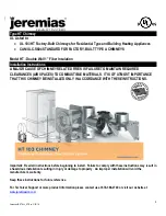
Product Code Key
Each part manufactured by Jeremias is identified with a product code. The product code contains the Model, Vent size, Part ID, and Other
information.
Part Number Example:
HT
06
-
SS
12
|
|
|
|
Model
Chimney
Diameter
Material
Product ID
5" to 8"
SS = 316ss Inner / 304ss outer
GAL = 316ss Inner / Galv Outer
Product ID
AD = Chimney Adapter
LB = Locking Band
CSRT = Round Ceiling Trim
AP = Anchor Plate
12 =
12” Length
SA = Spark Arrestor
IS = Attic Insulation Shield
18 = 18” Length
SC = Storm Collar
RC = Rain Cap
24 = 24” Length
TWC = Tee with Cap
ELKT = Elbow Kit (Degree)
36 = 36” Length
CSS = Ceiling Support Square
ELS = Elbow Strap
48 = 48” Length
TS = Tee Support
ERB = Extended Roof Brace
AVL = Adjustable Vent Length
WB = Wall Bracket
FRS = Firestop Radiation Shield
RS = Roof Support
WT = Wall Thimble
FRF = Flat Roof Flashing
RST = Trim Collar
PRF = Pitched Roof Flashing
CSR = Round Ceiling Support
General Installation Requirements
•
Except for installation in one or two-family dwellings, a factory-built chimney system that extends through any zone above that on which the
connected appliance is located, shall be provided with an enclosure having a fire resistance rating equal to or greater than that of the floor
or roof assemblies through which it passes.
•
Chimney to be sized in accordance with the appliance manufacturer’s instructions.
•
Parts of the chimney system below the roofline should be enclosed to help reduce condensation, creosote buildup and improve draft.
•
Creosote and soot
–
formation and need for removal: When wood is burned slowly, it produces tar and other organic vapors, which
combine with expelled moisture to form creosote. The creosote vapors condense in the relatively cool chimney flue of a slow-burning fire.
As a result, creosote residue accumulates on the flue lining. When ignited this creosote makes an extremely hot fire. The chimney should
be inspected once every 2 months during the heating season to determine if a creosote or soot buildup has occurred. If creosote or soot
has accumulated, it should be removed to reduce the risk of chimney fire.
•
To clean and inspect: Open or remove termination cap or cleanout tee to access the chimney.
•
Contact local building or fire officials about restrictions and installation inspection in your area.
•
Every chimney system must be planned and installed for performance and safety.
•
Refer to the appliance manufacturer’s instructions to determine venting requirements and limitations with respect to the inst
allation and use
of the appliance.
•
Maintain rated clearances to combustibles over the entire length of the vent system.
•
Do not field install insulation in any required clearance around the chimney system
•
Reference the appliance manufacturer’s installation and operating guides
for maintaining ventilation and air circulation where required
•
For planning and clearance purposes, nominal OD of chimney always equals ID plus 2”, example = 6” Chimney OD is 8”
•
Not all appliances are listed for use in mobile homes and may require special considerations. Refer to the appliance safety manual
carefully.
Termination Requirements
In accordance with National Fire Protection Association Standard #211, the chimney must terminate at least 3 feet above the roof top penetration
and 2 feet higher than any structure within a 10-ft. radius (see Fig 17). Chimney heights greater than 5 feet above the roof line must use additional
support bracing. See Telescopic Roof Brace (TRB) section for instructions.


