background image

21

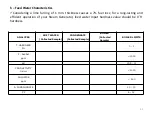
ANALYZES

SOFT WATER

(Collected Sample)

CONDENSATE

(Collected Sample)

BOILER

(Collected 

Sample)

BOILER LIMITS

T. HARDNESS

Fr

0

0 - 1

ALKALI

ppm

< 1300

pH

10,5 - 12

CONDUCTIVITY

Us/cm

< 1000

CHLORIDE

ppm

< 500

A. PHOSPHONATE

10 

15

CF

6 - 12

Feed Water Characteristics

Considering a lime furring of 1 mm. thickness causes a 7% fuel loss; for a long-lasting and

efficient operation of your Steam Generator, feed water input hardness value should be 0

˚Fr

hardness.

Содержание SHS Series

Страница 1: ...SHS SERIES STEAM GENERATORS ISIEV Makina Sanayi ve Ticaret Limited irketi kitelli OSB Eskoop Sanayi Sitesi C7 4 Blok No 479 Ba ak ehir stanbul T RK YE Tel 90 212 595 16 56 Fax 90 212 595 42 39 www je...

Страница 2: ...15 J Water Softening Device Connection Optional 16 USAGE AND MAINTENANCE INSTRUCTIONS 17 a Introduction 17 b Warnings 17 c Warranty and Service 18 d General Characteristics 18 e Operation Conditions...

Страница 3: ...h Steam Production kg h Burner Type Fuel Operation Principle Control Panel ISIEV Project Number Power Needed V Hz kW Thermostat Thermocouple Feed Pump Type Drive Motor d d kW Pressure Switches Safety...

Страница 4: ...ine e pressure hull burner electric control panel feed water pump separator condensate tank and smokestack sections As seen in the picture the coil serpentine consists of two intertwined spirals The i...

Страница 5: ...ondensate installation water installation electricity installation blowdown installation and smokestack connection to our company 5 The steam generator must be located in a well ventilated frost free...

Страница 6: ...nk Use a heater on the preheating tank Use valve and filter on the fuel feed installation The fuel tank must be located at a level which is proper to the burner Place the fuel tank at least 5 meters a...

Страница 7: ...burner on the gas inflow line of the burner In the gas installation a valve should be used near the burner Gas installation and connections should be checked and the gas should be opened by the gas di...

Страница 8: ...generator smokestack outlet to the smokestack the connection from the generator to the smokestack must be provided with a 10 slope which will facilitate the discharge of the exhaust gas RNEK BACA BAGL...

Страница 9: ...0 80 100 100 125 Vapor Connection Measurements According to Capacities In cases where more than one point of steam should be taken from steam generator steam distribution collector should be made Coll...

Страница 10: ...Steam Distribution Connection Diagram 10 Buhar Da l m Kollekt r...

Страница 11: ...sary installation slopes Use suitable types and diameters of steam traps on your machine s condensate outlets Condensate return diameters should be one diameter less than the diameter of gas installat...

Страница 12: ...Condensate Return Connection Diagram 12...

Страница 13: ...he electrical control panel Electrical control panel and external grounding of the device are made by our factory All the user has to do is enter the external grounding at the specified point on the e...

Страница 14: ...he vent installation will be made should not be smaller than the connection port diameter left on the condensate tank and must be the same diameter or above Vent connection should be made in such a wa...

Страница 15: ...15 Vent Connection and Blowdown Connection Diagram...

Страница 16: ...ty valve should be installed without making any links to another installation connections If the present location is favorable safety valve installation should be made with a slope towards outside wit...

Страница 17: ...vices require water and water pressure for regeneration Inlet water pressure must be min 3 and max 6 bars If the mains water is not at the desired pressure a storage tank and a booster must be positio...

Страница 18: ...rding to EN 676 Gas Fired according to the Gas Burners Directive should be used Feed water characteristics to be used in steam generators must meet the specified criteria The use of soft clean and non...

Страница 19: ...6 Annex 2 Article 2 11 there is no harm in placing it in the building without a separate boiler room It has a highly advanced security equipment The body of the steam generator is insulated by coverin...

Страница 20: ...fuel options in gas fuels Do not under any circumstances change the settings of the fuel units of your device other than these types of fuel g Commissioning Controls to be done before commissioning Pe...

Страница 21: ...0 1 P ALKALI ppm 1300 pH 10 5 12 CONDUCTIVITY Us cm 1000 CHLORIDE ppm 500 A PHOSPHONATE 10 15 CF 6 12 h Feed Water Characteristics Considering a lime furring of 1 mm thickness causes a 7 fuel loss fo...

Страница 22: ...le giving the condensate return to the external environment for a period of half to one hour will ensure that these steam drained wastes are discharged If the condensate return cannot be given out it...

Страница 23: ...above the set value of the operating switch Stops burner when activated Safety Valve The safety valve is set at 1 bar above the working pressure of the safety switch This process is carried out during...

Страница 24: ...return of the goods price reduction in defect rate or replacement of the goods If the product fails within the warranty period the period spent in repair is added to the warranty period The fault is...

Страница 25: ...e water must be performed and 00 F should be seen The higher the quality of the water you use the longer the service life of your steam generator will be When performing hardness analysis Fill the sam...

Страница 26: ...ng to the burner is connected For gas fired appliances check the gas pressure at the inlet of the burner Figure 4 3 Check the condensate tank for water Check that the tank is full from the condensate...

Страница 27: ...should be opened It should be checked whether the valve on the line supplying the feed water pumps from the condensate tank is open In addition valves outside the steam generator in the boiler room mu...

Страница 28: ...oil is checked from the Speck pump dipstick The pump oil level is normal at the points between the top and bottom paddles of the dipstick If there is a decrease in the oil level or if water has been...

Страница 29: ...fers to the field of application must be use as pump oil Remove the yellow blind plugs shown in Figure 8 and drain the oil in the pump After the oil is completely filtered the blind plugs are closed a...

Страница 30: ...Close the main steam valve 30 2 Open the steam trap by pass valve lk al t rma Vanas by pass A k Pozisyon 3 Switch on the main switch and supply electricity to the system 4 Turn on the burner switch o...

Страница 31: ...operation of the pump The pump will start to fill the coil Continue this process until the first start up valve By Pass receives water Note The first start valve is kept open to check that the coil is...

Страница 32: ...steam generator capacity If higher pressures are encountered this is a precursor to the formation of blockage in the coil Gliserinli Pompa Manometresi 7 You should see water coming from the outlet of...

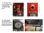
Страница 33: ...he burner will start operating Check the burner flame through the sight glass Br l r G zetleme Cam 10 Wait until the steam temperature reaches 105 C and the water from the bypass valve outlet runs out...

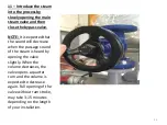
Страница 34: ...cted that the sound will decrease when the passage sound of the steam is heard by opening the valve slightly When the volume decreases the valve opens a quarter turn and the volume is expected to decr...

Страница 35: ...p switch on the electrical control panel to Manual Manuel 2 After the pressure value on the steam manometer is 0 Close the main steam valve Open the steam trap by pass valve Let the pump run until wat...

Страница 36: ...outlet turn the pump control switch off via the electric control panel 4 Turn the burner control switch on the electric control panel to the off position 5 Cut the power by turning off the main switch...

Страница 37: ...n come to see the error code of the device check and eliminate the malfunction then reset and run the device again Failure Indicator Fault Codes Fault Nb 1 High Pressure Fault Nb 2 High Vapor Temperat...

Страница 38: ...operating pressure The operating pressure switch may fail and the device may rise above the set pressure reaching the value of the safety pressure switch Defective pressure switch must be replaced Th...

Страница 39: ...am Generally it is caused by not feeding the required amount of water into the device z m The setpoint of the steam temperature thermostat must be checked The setpoint of 190 0C might have been decrea...

Страница 40: ...ply system is clean Check that the pressurization pump in front of the device feed water pump Speck pump is operating The hydrometer at the pump outlet will help you understand whether the pump is wor...

Страница 41: ...emoving the blind plugs on the horizontal we remove the check valve groups inside the opened section by pulling them outwards 3 We also remove the springs on the back of each of the check valve groups...

Страница 42: ...smokestack temperature In general this fault is caused by the burner combustion settings being distorted or set to high capacities Solution The setpoint of the smokestack temperature thermostat must...

Страница 43: ...layed refer to the inverter s main display The fault code printed on the inverter main screen must be checked in the inverter fault codes manual in the device operating instructions folder Solution So...

Страница 44: ...ompa Termi i Fault Code Indicator Solution Install the pressurization pump thermal inside the electrical control panel The thermal is installed by pressing the blue button as shown in the picture Make...

Страница 45: ...et the burner must be re engaged and illuminated after a series of checks When it fails again the same process is repeated several more times and the burner is restarted The burner must be checked if...

Страница 46: ...the strainer on the pump suction line may be clogged it must be cleaned Make sure that the pressurization pump supplies water The feed pump may not supply water Speck pump check valves can be contamin...

Страница 47: ...eration valve Fault Nb 5 Inverter Malfunction Indicates the inverter is signaling an error and no power to the pump See the inverter error codes in the operating instructions folder Fault Nb 6 Pressur...

Страница 48: ...d be between 1 3 bars depending on the steam generator capacity If higher pressures are encountered this is an indication that the coil serpentine has started to block 7 You should see water coming fr...

Страница 49: ...ing device salt tank STEAM GENERATOR DAILY WEEKLY AND MONTHLY MAINTENANCE JENESIS SHS SERIES STEAM GENERATOR DAILY CONTROL AND MAINTENANCE Water Softening Device Salt Tank 2 Check that water is coming...

Страница 50: ...at the desired hardness After manual washing of the water softener fill the condensate tank when the hardness value is reached Water Softening Device Manual Regeneration Button ATTENTION During the da...

Страница 51: ...ATOR WEEKLY CONTROL AND MAINTENANCE 1 Check the salt level by opening the lid of the water softener salt tank and add salt if necessary Water Softening Device Salt Tank 2 Open and clean the filter at...

Страница 52: ...he condensate tank cap cuts off the mains water after the level is reached 4 Clean the dirt trap on the fuel line Gas Filter Liquid Fuel Filter 5 Remove and clean the sight glass The front nut of the...

Страница 53: ...ter in the direction of the screw discard the filter inside and insert a new one and tighten the body nut Open the inlet valve again Inlet Valve Bleeder Screw Purger Body Nut 7 Clean the trap group di...

Страница 54: ...the salt tank of the water softener The salt dissolved in the salt tank causes contamination on the surface of the tank over time Empty the salt tank before cleaning the tank To disconnect the salt ta...

Страница 55: ...55...

Страница 56: ...56...

Отзывы: