background image


12 

3.4. Items to be checked after installation. 

S/N 

Check items 

YES  NO 

Are the posts vertical to the floor? 


Is the oil hose well connected? 


Is the steel cable well connected? 


Are two platforms well connected? 


Are electrical connections, right? 


Are the rest joints firmly screwed? 


Are all items need lubricating added with grease? 


4. Operation instructions 

4.1 Precautions   

4.1.1 Check all the joints of oil hose. Only when there is no leakage, the lift can start work.   

4.1.2 The lift, if its safety device malfunctions, shall not be used. 

4.1.3 The machine shall not lift or lower an automobile if its center of gravity is not positioned midway of the platforms. Otherwise, 

the Jema Autolifte as well as our dealers will not bear any responsibility for any consequence resulted thereby. 

4.1.4 Operators and other personnel concerned should stand in a safety area during lifting and lowering process.   

4.1.5  When  the  platforms  rise  to  the  desired  height,  switch  off  the  power  at  once  to  prevent  any  mal  operation  done  by 

unconcerned people. 

4.1.6. Make  sure  the  safety  lock  of  the  lift  is  engaged  before  start  working  under  the  vehicle  and  no  people  under  the  vehicle 

during lifting and lowering process. 


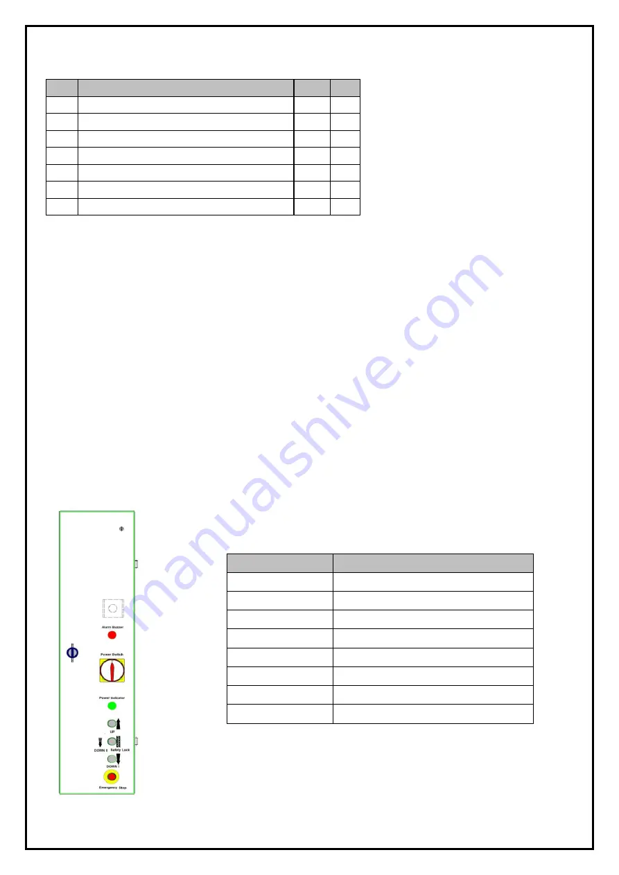
4.2 Descriptions of control box 


Description   

Function   

Alarm buzzer   

Low height alarm   

Power switch   

Control power connection   

Power indicator   

Show if power is connected   

UP button   

Control the UP movement   

Safety lock   

Safety lock engaged   

DOWN I button   

Control down movement   

DOWN II button 

Control down movement 

EMG.Stop 

Ensure safety in emergency conditions   

Содержание JA5500F

Страница 1: ...Jema Autolifte A S JA5500F FOUR POST LIFT Electrical Release INSTALLTION OPERATION AND MAINTENANCE MANUAL Read this entire manual carefully and completely before installation and operation of the lift...

Страница 2: ...installation 3 3 Installation 3 4 Items to be checked after installation 4 Operation instructions 12 15 4 1 Precautions 4 2 Descriptions of control box 4 3 Flow chart for operation 4 4 Operating inst...

Страница 3: ...formation on the nameplate Model No ____________________________ _ Serial No ___________________________ Production Date ______________________ __ The following specially trained people are permitted...

Страница 4: ...allation Date __________________ ________ _ _ Declaration The above mentioned lift has been correctly installed and all its functions including the reliability of safety locks have passed strict tests...

Страница 5: ...not leave the controls while the lift is still in motion 1 3 4 Keep hands and feet away from any moving parts Keep feet clear of the lift when lowering 1 3 5 Only properly trained personnel can opera...

Страница 6: ...afety warning signs attached on the lift are for the purpose of drawing the user s attention to safety operation The labels must be kept clean and need to be replaced when they are worn out or have dr...

Страница 7: ...raulic oil cylinder and a set of power unit It is driven by an electro hydraulic system Up and down of platforms is controlled by the to and fro movement of the oil cylinder To ensure ultra safety of...

Страница 8: ...ist installing upon the lack of some parts Jema Autolifte A S as well as our dealers will not bear any responsibility for this and will charge for any parts subsequently demanded by the buyer 3 1 3 Gr...

Страница 9: ...he ground 2 Have the platforms of the lift suspended by a crane and then screw off the upside bolt and remove the first platform on to the wooden battens initially prepared 3 Screw off the downside bo...

Страница 10: ...it through the reserved 21 hole on the top of the post and then screw on the M20 nut Step8 Fit on 8 nylon sliders see the following diagram Step9 Fix the ramps Align the end of the platform and the h...

Страница 11: ...post it is important that they are mounted correctly as otherwise they can break when the lift is tested See picture below how to place them in the main post Also remember to adjust the arm on the to...

Страница 12: ...e Jema Autolifte as well as our dealers will not bear any responsibility for any consequence resulted thereby 4 1 4 Operators and other personnel concerned should stand in a safety area during lifting...

Страница 13: ...3 Switch on When the power indicator is on press the UP button until platforms rise to the desired height 4 Before performing any service around or under the vehicle operators must press the safety l...

Страница 14: ...rods 2 Press and screw loose counter clockwise the unloading valve to lower the platform In the case the safety lock is fully engaged 1 Remove the fitting as show in the following pictures and connec...

Страница 15: ...agnets under the cross beam to have the four safety blocks released from the safety rods 3 Press and screw loose counter clockwise the unloading valve to lower the platform Unloading valve Safety bloc...

Страница 16: ...s damaged Replace it Oil level is too low Add oil The oil hose became loose or dropped off Tighten it The cushion valve became loose or jammed Clean or adjusts it Platforms go down slowly after being...

Страница 17: ...y checking items Check the flexibility of moving parts Check the working conditions of safety parts Check the amount of oil left in the oil tank Oil is enough if the carriage can be raised to highest...

Страница 18: ...lider holder JA4000FN A2 B2 8 14 Manual rod JA4000FM A29 1 15 Pump assembly holder JA4000FN A13 1 16 Protector JA4000FN A2 B5 4 17 Post cover JA4000FN A11 4 18 Shaft JA4000FN A8 B2 2 19 Handle JA4000F...

Страница 19: ...19 Annex2 Overall diagram...

Страница 20: ...20 Annex3 Floor plan Annex 4 Steel cable connection...

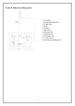
Страница 21: ...nder 3 Electrical unloading valve 4 Throttle valve 5 Motor 6 Coupling 7 Gear pump 8 One way valve 9 Overflow valve 10 Anti surge valve 11 Cushion valve 12 Emergency unloading valve Annex 5 Hydraulic w...

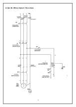
Страница 22: ...22 Annex 6 Wiring diagram Three phase...

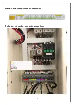
Страница 23: ...23 Electric wire connections in control box Picture of the control box and connections...

Страница 24: ...24...

Страница 25: ...25...

Страница 26: ...26...

Страница 27: ...27 Annex7 Separate diagrams for the lift JA5500F...

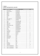
Страница 28: ...00FN A2 B4 4 21 261021 Shaft 3 JA5500FN A3 B12 4 22 262004 Slider JA5500FN A2 B3 8 23 261082 Slider holder JA5500FN A2 B2 8 24 261081 Small sheave JA5500FN A3 B5 4 25 219010 Circlip 16 12 26 261101 Sa...

Страница 29: ...28068 216006 261501 56 261077 Pin JA5500FN A22 4 60 262011 Ball disk holder JA5500FN A20 6 61 628008 Guiding plate welding JA5500FN A8 B1 2 62 252025 Small rotor wheel MR30 A22 B5 4 63 428065 Shaft JA...

Страница 30: ...30 S N Material Name Spec Drawing Qty Note 85 215032 211101 Cross round headed bolt Inside hex flat headed bolt M5 12 M8 20 6 86 334032 Main plug P32J3R 8 2 628317 JA5500FN A5 1 628007 1 1...

Страница 31: ...V 24V Pcs 1 6 320115 Transformer JBK3 400VA 230V 24V Pcs 1 Same outlook as item 5 7 320116 Transformer JBK3 400VA 240V 24V Pcs 1 Same outlook as item 5 8 320087 Transformer JBK3 400VA 380V 24V Pcs 1 S...

Страница 32: ...MQB3 10 20 AC24V Pcs 4 17 322010 Emergency stop Y090 11ZS red Pcs 1 18 324022 Alarm buzzer AD17 22SM DC24 Pcs 1 19 336012 Bridge rectifier KBPC5A 35A Pcs 1 20 335007 Capacitor 4700UF 50V Pcs 1 21 328...

Страница 33: ...29 334034 Main plug P32K3R Pcs 1 30 321024 Limit switch YBLX ME8104 Pcs 6 Spare parts list for the hydraulic system S N Material Name Spec Unit Qty Picture 1 N A Hydraulic block YF 2 Pcs 1 2 313042 El...

Страница 34: ...e hex fitting M14 1 5 Pcs 2 8 333022 Tie in of the pump M14 1 5 G1 4 inside swivel Pcs 1 9 313015 Coupling YL A Pcs 1 10 312106 Gear pump CBK F330 Pcs 1 11 313030 Oil absorbing pipe YX B 270 Pcs 1 12...

Страница 35: ...35 Annex9 Size and weight requirements on vehicles...

Страница 36: ...36...

Отзывы: