background image


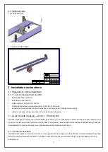
2.3 Optional parts   

1. Jacking beam light                                                                         


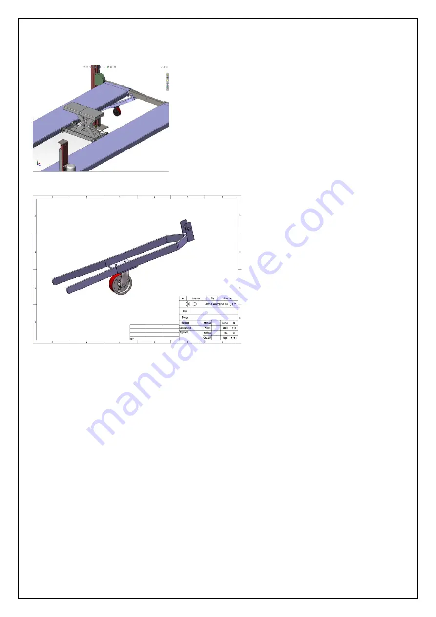
2. Mobile Kit (OPTIONAL) 


3. Installation instructions 

3.1 Preparations before installation 
3.1.1 Tools and equipment needed. 


Appropriate lifting equipment 


Anti-abrasion hydraulic oil.   


Rotary Hammer Drill with 3/4’’ drill bit. 


Chalk and tape measure, magnetic plump, 8 meters ø15 level pipe. 


Sockets and open wrenches, a set of inside hex wrenches, cross and straight screw drivers. 


Hammer, 4pounds,


sharp nose pliers,


ø17,ø19,ø22 socket spanners


3.1.2 List for parts checking ---Annex 1

Packing list


Unfold the package and check if any parts missed as per Annex 1. Do not hesitate to contact us in case any parts missed, but  if 

you do not contact us and insist installing upon the lack of some parts, Jema Autolifte A/S as well as our dealers will not bear any 

responsibility for this and will charge for any parts subsequently demanded by the buyer.   

 
3.1.3 Ground conditions   

The lift should be fixed on a smooth and solid concrete ground with its strength more than 3000psi, tolerance of flatness less than 

5mm and minimum thickness of 200mm. In addition, newly built concrete ground must undergo more than 28days

’ cure and 

reinforcement. 


Содержание JA4000FP

Страница 1: ...JA4000FP FOUR POST LIFT Capacity 4000KG Manual Release INSTALLTION OPERATION AND MAINTENANCE MANUAL Read this entire manual carefully and completely before installation and operation of the lift ...

Страница 2: ... installation 3 3 Installation 3 4 Items to be checked after installation 4 Operation instructions 12 15 4 1 Precautions 4 2 Descriptions of control box 4 3 Flow chart for operation 4 4 Operating instructions 4 5 Emergency lowering in case of no power 5 Trouble shooting 15 16 6 Maintenance 16 17 7 Annex 18 21 Annex1 Packing list of the whole lift Annex2 Overall diagram Annex3 Floor plan Annex4 Ste...

Страница 3: ...nformation on the nameplate Model No ____________________________ _ Serial No ___________________________ Production Date ______________________ __ The following specially trained people are permitted to operate and maintain this lift 1 2 3 4 5 6 7 8 9 10 ...

Страница 4: ...tallation Date __________________ ________ _ _ Declaration The above mentioned lift has been correctly installed and all its functions including the reliability of safety locks have passed strict tests Therefore we hereby declare that this lift is in normal working condition when installation finished Installation date Installer s signature User s signature ...

Страница 5: ...3 Do not leave the controls while the lift is still in motion 1 3 4 Keep hands and feet away from any moving parts Keep feet clear of the lift when lowering 1 3 5 Only properly trained personnel can operate the lift 1 3 6 Do not wear unfit clothes such as large clothes with flounces tires etc which could be caught by moving parts of the lift 1 3 7 To prevent evitable incidents surrounding areas of...

Страница 6: ...safety warning signs attached on the lift are for the purpose of drawing the user s attention to safety operation The labels must be kept clean and need to be replaced when they are worn out or have dropped Read the explanations of the labels carefully and try to memorize them ...

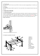
Страница 7: ... hydraulic oil cylinder and a set of power unit It is driven by an electro hydraulic system Up and down of platforms is controlled by the to and fro movement of the oil cylinder To ensure ultra safety of operators it is equipped with mechanical safety locks in the four posts which will be manually engaged in the process of lifting so as to prevent the platforms from sudden dropping down in case th...

Страница 8: ...2 List for parts checking Annex 1 Packing list Unfold the package and check if any parts missed as per Annex 1 Do not hesitate to contact us in case any parts missed but if you do not contact us and insist installing upon the lack of some parts Jema Autolifte A S as well as our dealers will not bear any responsibility for this and will charge for any parts subsequently demanded by the buyer 3 1 3 ...

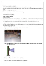
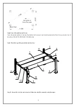
Страница 9: ...oncrete or on a second or an elevated floor without first consulting building architect Make sure that the space around or over the lift should be free of obstructions like heaters building supports electrical lines etc Step 2 Fix the installation layout Once the installation site is determined mark first the standing point of the four posts by a tape measure and chalk Ensure two diagonal lines ar...

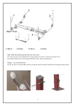
Страница 10: ...ntion that the runway for jack should be placed inside Mount the car protection in front of the platform Connect the other beam in the same way Step 9 Mount the top of the post with showed direction Step 10 Connect the steel wire and release bar Release bar should be mounted nearby the engine ...

Страница 11: ...ose if applicable from the main platform and have them connected to the hydraulic block Then fix the hydraulic pump on to the plate by M10 30 hex bolts spring and flat washers Step 12 Connect the limit switches The two wire plug is for top limit switch and four wire plug for bottom limit Mount the limit switch according to below pictures ...

Страница 12: ...structions 4 1 Precautions 4 1 1 Check all the joints of oil hose Only when there is no leakage the lift can start work 4 1 2 The lift if its safety device malfunctions shall not be used 4 1 3 The machine shall not lift or lower an automobile if its center of gravity is not positioned midway of the platforms Otherwise Jema Autolifte A S as well as our dealers will not bear any responsibility for a...

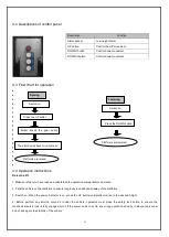
Страница 13: ...tforms to ensure its gravity is positioned midway of the platforms 3 Switch on When the power indicator is on press the UP button until platforms rise to the desired height 4 Before perform any service around or under the vehicle operators must press the safety lock button to ensure the mechanical safety lock is fully engaged turn off the power so as to avoid any wrong operation done by irrelevant...

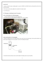
Страница 14: ...ock is not fully engaged 1 Push the release bar and make sure all four locks are off 2 Press and screw loose counterclockwise the unloading valve to lower the platform In the case the safety lock is fully engaged 1 Remove the fitting as show in the following pictures and connect the tie in with hand pump Pull and push the handle of the hand pump to supplement oil to the oil cylinder so as to have ...

Страница 15: ...mit switch Motor runs but will not rise The motor run reversely Check the wire connection Overflow valve is loose or jammed Clean or adjust it The gear pump is damaged Replace it Oil level is too low Add oil The oil hose became loose or dropped off Tighten it The cushion valve became loose or jammed Clean or adjusts it Platforms go down slowly after being raised The oil hose leaks Check or replace...

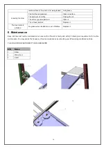
Страница 16: ...lace it The steel cable is abraded No grease when installation or out of lifetime Replace it 6 Maintenance Easy and low cost routine maintenance can ensure the lift work normally and safely Following are requirements for routine maintenance You may decide the frequency of routine maintenance by consulting your lift s working conditions and time THE FOLLOWING PARTS NEED TO BE LUBRICATED S N Name 1 ...

Страница 17: ...f safety parts Check the amount of oil left in the oil tank Oil is enough if the carriage can be raised to highest position Otherwise oil is insufficient Check whether plug bolts firmly screwed 6 3 Monthly checking items Check whether plug bolts firmly screwed Check the tightness of the hydraulic system and screw firm the joints if it leaks Check the lubrication and abrasion circumstance of axial ...

Страница 18: ...18 7 Annex Annex1 Packing list of the whole lift Annex2 Overall diagram ...

Страница 19: ...19 Annex3 Floor plan ...

Страница 20: ...20 Annex 4 Steel cable connection ...

Страница 21: ...21 ...

Страница 22: ...22 ...

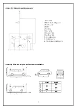
Страница 23: ...ding valve 4 Throttle valve 5 Motor 6 Coupling 7 Gear pump 8 One way valve 9 Overflow valve 10 Anti surge valve 11 Cushion valve 12 Emergency unloading valve Annex 5 Hydraulic working system Annex6 Size and weight requirements on vehicles ...

Страница 24: ...24 ...

Страница 25: ...25 ...

Отзывы: