32 Operation and Control Instructions
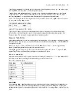
Timing
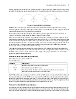
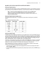
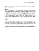
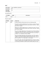
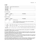
When a channel address is strobed in from the data lines, the reset command is strobed in from the
/Reset line. The Error line goes high if the reset function cannot verify the position of the switching
mechanism (Figure 10).
Figure 10: Timing Diagram
Timing Key
The timing key symbols and values are listed in Table 10.
Table 10: Timing Key
Symbol
Minimum
Maximum
tdh, data hold time
20 µs
–
tstr, strobe pulse width
1 µs
–
tmv, switching cycle time
–
0.55 ms
trh, reset hold time
20 µs
–
trst, reset cycle time
–
1.1 s
Busy
Error
Содержание SKB Series
Страница 1: ...SKB SERIES FIBEROPTIC SWITCH MODULE User Manual ...
Страница 2: ...ii 10109002 Rev 001 August 2001 2001 JDS Uniphase All rights reserved ...
Страница 4: ...iv ...
Страница 11: ...7 Contents ...
Страница 13: ...9 List of Figures ...
Страница 15: ...11 List of Tables ...
Страница 19: ...4 Safety Information Instructions and Symbols ...
Страница 25: ...10 Introduction ...
Страница 53: ...38 Operation and Control Instructions ...
Страница 91: ...76 Commands ...
Страница 111: ...96 Application Notes ...
Страница 113: ...98 Service ...


