24 Operation and Control Instructions
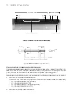
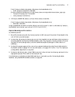
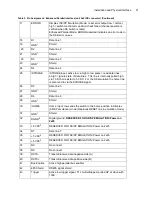
For the SKB product, power may be applied by two methods. It may be applied to the 4x1 Power
Connector, OR it may be applied on the Power Pins of the IDE 2x25 Connector. The method of
implementation will be determined by the customer system design requirements.
Examples of system level requirements for using the Power Connector (4x1):
•
The SKB is located at a significant distance from the supply and/or temperature extremes are
expected, hence heavier gauge wiring is required to ensure an adequate voltage level at the
SKB unit.
•
When harnessing multiple SKB units to a common supply.
Examples of system level requirements for using the power pins on the IDE 2x25 connector:
•
Ease of assembly during manufacturing where a flat cable (generally 50 pin) is used (see
note 1).
•
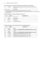
Implementation in Simplex (SK/SP Emulation) Mode where a 26 pin flat cable (like the SK/SP
product) is used (see note 1).
•
When mounting the SBK product on a PCB.
Connecting Power
When designing the system, it is important to note that:
1. The +5VDC required by the SKB switch is to be measured at the connector of the SKB unit itself,
not the power source. This is particularly important when the SKB is expected to operate over a
wide temperature range or is located at a distance from the power source (i.e. applications where
system conditions are such that the voltage drop over the harness might exceed the SKB switch
specifications).
2. Only one of the two means of power connection should be employed at one time.
Architecture Overview of the RS485 Serial and Enhanced Parallel Interfaces
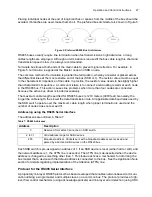
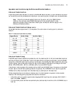
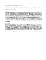
On the RS485 Serial and Enhanced parallel interfaces, instructions and queries are received by the
SKB module as command packets. Command packets describe a method of encapsulating a com-
mand opcode, a length code, and applicable parameter data in a format that can be interpreted by
the SKB.
Command Packet Format
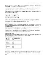
Multi-byte communication with the SKB module, via the RS485 Serial and Enhanced Parallel inter-
faces, is accomplished via command packets.
A standard command packet can be up to 255 bytes in length.
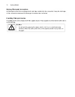
Caution
•
Protection against reverse connection of the power input is not incorporated
in the SKB switch. Reverse connection of the power input results in damage
to the switch.
•
The SKB switch requires that the power input be within the tolerance given at
the unit. Care needs to be exercised in the design of the system power to
compensate for any wiring losses in cabling. Failure to maintain the correct
supply voltage can result in unpredictable operation of the switch.
Содержание SKB Series
Страница 1: ...SKB SERIES FIBEROPTIC SWITCH MODULE User Manual ...
Страница 2: ...ii 10109002 Rev 001 August 2001 2001 JDS Uniphase All rights reserved ...
Страница 4: ...iv ...
Страница 11: ...7 Contents ...
Страница 13: ...9 List of Figures ...
Страница 15: ...11 List of Tables ...
Страница 19: ...4 Safety Information Instructions and Symbols ...
Страница 25: ...10 Introduction ...
Страница 53: ...38 Operation and Control Instructions ...
Страница 91: ...76 Commands ...
Страница 111: ...96 Application Notes ...
Страница 113: ...98 Service ...


