DSC260 Preliminary Owners Manual
Revision 0.9
4
4.0
General Operation
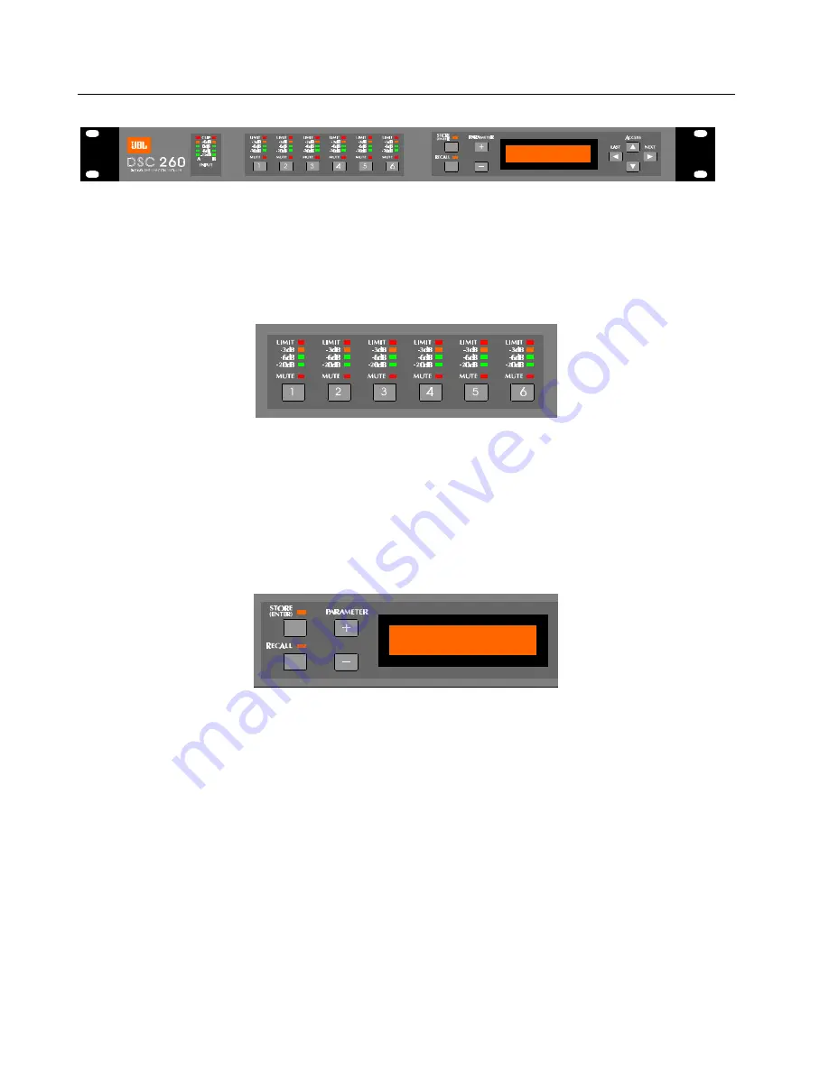
Figure 2 DSC260 Front Panel
4.1 LED Input Bargraphs The input bargraphs are peak responding to the input signal and also indicates digital clipping. The inputs always
show the input level as calibrated to the XLR inputs. i.e. (+20 dBu=Maximum Input) -3dB, -6dB, -12dB and a signal present
show the level below maximum input. In addition, the “Clip” lights function both as analog input “Clip” indicators and signal if there
is clipping in the Digital Signal Path. If both A & B “Clip” LEDs flash yet a yellow -3 does not, this would indicate that the DSP is
clipping and not the analog input circuitry. This situation would most likely be caused by excessive digital gain or EQ in one or
more outputs.
Figure 3 Output Bargraphs and Mute
4.2 LED Output Bargraphs: The output bargraphs 0dB headroom reference is shifted with respect to the limiter settings. In this way, each
output can be set to reflect the specific level below maximum for the respective output. i.e. If a limiter is set to +8, then the
“Limit” LED represents an output of +8dBu and the -3, -6 and -20dB LEDs refer to this level and s5, +2 and -12dBu,
respectively. This relationship remains regardless of output gain settings as the limiters are the final element in the programming
path. As an example, if a +4dBu signal is routed to an output and the gain is set to 0dB and the limiter is set to +10dBu, then the
-6dB Led would light indicating 6 dB of headroom. (+10dBu - (4 + 0)dBu = 6dB)
4.3 Mute: Pressing any of the front panel Mute keys will toggle the respective channel in and out of mute. The LED will reflect the mute
status. A Red LED on signifies the output is muted.
Figure 4 Store, Recall and Parameter Adjust
4.4 Store(Enter) and Recall: These keys allow the user to store and recall programs from the internal memories. The Store key is also
used as an Enter Key to confirm certain operations such as a configuration change from 2 way to 3 way, MIDI Dump and OEM
hiding which are explained further in Section 5.0 on Utility Control Parameters.
4.5 Plus and Minus: These keys adjust the currently selected parameter up or down. In the case of a non-numeric parameter, these keys
scroll through a predefined set of variables.
4.6 LCD Display Screen: This 2 x 16 character LCD displays all required programming information. It is, in effect, a window into a large
grid of adjustable parameters that moves from row to row and column to column. Figure 5 below as well as the back of this
manual is a diagram of the programming grid. Upon turn on, the software revision will also appear briefly. The bottom line shows
the program number and name of the stored program. An asterisk indicates that a program has been edited since the last store.
This shown in the top right of the LCD display on all screens except the default.


