background image

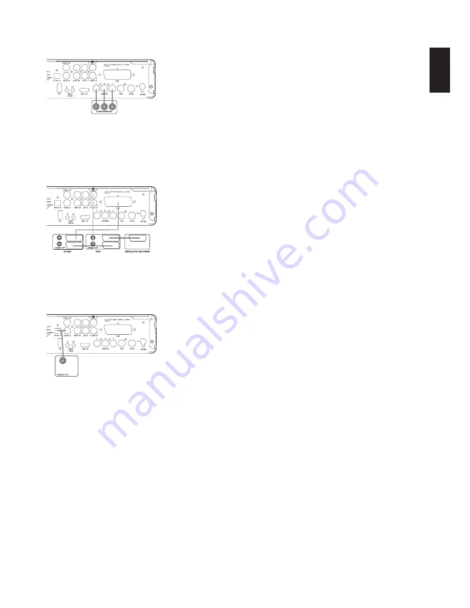
Connecting VCR and Sat Decoder (Methods 5 and 6)

The diagram below shows possible connection methods for
common system configurations. These are intended as guidelines
only. Due to differences in equipment specifications, the method of
connection for your equipment may be different from that shown.
Please consult the owner’s manual for your equipment for further
guidance.

Connecting Set-Top Box or Digital Satellite Receiver (Method 7) –
Using Coaxial Digital Cable

To listen to the digital multichannel signal or downmix from set-top
boxes or digital satellite receivers, connect the Coaxial Digital Out
of your device to the 

Coaxial Digital In

8

on the CS receiver.

Optional Audio Connections

Aux Input for External Source

You may connect a line-level stereo analog audio source such as a
Sat receiver, tape deck, phono preamp of a record player, etc., to
the receiver’s rear-panel 

Audio In Input

6

sockets to enjoy the

benefits of your CS system with other source components.

• VCR Connection-Audio (cables not Included): To listen to the

sound from your stereo VCR through the speakers of this system,
connect the Left/Right audio output jacks of your stereo VCR to
the Left/Right audio input jacks 

Audio In

6

of this system.

Aux Output for Recording

To record the sound of the CS system with your VCR or any audio
recording device (tape deck, MD, CDR and some others), the 

Audio

Out Jacks

A

should be connected to the analog Record In jacks of

the appropriate device. They can also be connected to any audio
input on your TV to listen to the sound of your CS receiver through
the speakers of your TV only, when the amp in your subwoofer is
turned off and the volume of the CS receiver has been turned down
completely. If the speakers of your CS system are active, the
volume on your TV should be turned down.

Digital In- and Outputs

Connect the digital output of any digital sources such as an
optional CD or DVD changer or player, advanced video game, a
digital satellite receiver, HDTV tuner or digital cable set-top box or
the output of a compatible computer sound card to the 

Optical

and

Coaxial Digital Inputs

89

.

Connect the 

Coaxial Digital Output 

E

on the rear panel of the CS to

the matching digital input connections on a CD-R or MiniDisc recorder.

Note (When Connecting the Optical Digital Audio Cable – Optional):

Gently push the cable plug through the built-in shutter that covers
the optical digital audio output and connect the cable firmly so that
the configurations of both the cable and the connector match.

Speaker Placement

The placement of speakers in a multichannel home theater system
can have a noticeable impact on the quality of sound reproduced.

Depending on your viewing device, place the center speaker either
directly above or below your TV, or in the center behind a
perforated front-projection screen.

Once the center channel speaker is installed, position the left-front
and right-front speakers so that they are as far away from one
another as the center channel speaker is from the preferred
listening position. Ideally, the front-channel speakers should be
placed so that their tweeters are no more than 60cm above or
below the tweeter in the center channel speaker.

Depending on the specifics of your room acoustics, you may find
that imaging is improved by moving the front-left and front-right
speakers slightly forward of the center channel speaker. If possi-
ble, adjust all front loudspeakers so that they are aimed at ear
height when you are seated in the listening position.

Using these guidelines, you’ll find that it takes some experimenta-
tion to find the correct location for the front speakers in your
particular installation. Don’t be afraid to move things around until
the system sounds correct. Optimize your speakers so that audio
transitions across the front of the room sound smooth.

When the CS is used in 5.1-channel operation, the preferred
location for surround speakers is on the side walls of the room, at
or slightly behind the listening position.

15

English

INSTALLATION AND CONNECTIONS

Содержание Cinema Sound CS3

Страница 1: ...English CS3 CS5 DVD RECEIVER JBL CINEMA SOUND POWERED OWNER S GUIDE...

Страница 2: ...ment With Test Screen Player Radio Menu 23 Using the Status Bar Menu 23 Player Menu 23 Information Displays 23 Programmed Play Radio Menu 24 Rearranging the Station List 24 Selecting Presets 25 Removi...

Страница 3: ...be the first DVD player you ve owned Although many of the features of the DVD resemble those of standard CD players there are a num ber of functions with which you may be unfamiliar To ensure that you...

Страница 4: ...extremely hot or cold locations or an area that is exposed to direct sunlight or heating equipment Avoid moist or humid locations Do not obstruct the ventilation slots on the top of the unit or place...

Страница 5: ...bandwidth analog compres sion interlacing is employed first the odd numbered lines of a frame are displayed followed by the even numbered lines The result is that only half of the video image is drawn...

Страница 6: ...the format of certain discs it is possi ble that some discs may include a mix of features that are not com patible with the DVD Similarly although the DVD is capable of a wide range of features not a...

Страница 7: ...ortable hard disk for direct play back of audio image of video files or a USB hub The USB inputs are designed to power a single USB device at a time If additional hard disks are connected through a hu...

Страница 8: ...Indicators These indicators will light to show which source is currently selected H Repeat Indicators These indicators light when any of the Repeat functions are in use I VCD Playback Control Indicat...

Страница 9: ...al or a standard PCM digital source Do not con nect the RF digital output of an LD player to these jacks 9 Optical Digital Input Connect the optical digital output from a DVD player HDTV receiver LD p...

Страница 10: ...possible picture quality I Remote IR Output This connection permits the IR sensor in the receiver to serve other remote controlled devices Connect this jack to the IR IN jack on JBL or other compatib...

Страница 11: ...on Skip Step Previous Button Skip Step Next Button Play Button Search Slow Reverse Button Stop Button Search Slow Forward Button Macro Buttons Pic Pic Buttons Zoom Button Playlist Button Random Button...

Страница 12: ...rch speed changes as indicated by a number of arrows on the right top of your screen After pressing the Pause C button each press of this button will change the slow down speed as indicated by a numbe...

Страница 13: ...r ducts or leave it in a car parked in direct sunlight as there can be a considerable rise in temperature inside the car After playing store the disc in its case Do not write on the label side with a...

Страница 14: ...ting the TV and Optional Components NOTE To be able to listen to the sound of a live TV show through the loudspeakers of your CS system you need a connection between the audio output of your TV and th...

Страница 15: ...player advanced video game a digital satellite receiver HDTV tuner or digital cable set top box or the output of a compatible computer sound card to the Optical and Coaxial Digital Inputs 89 Connect...

Страница 16: ...receiver to begin final adjustments 1 Plug the Power Cable 4 into an unswitched AC outlet Note that the Power Indicator 1 will turn orange indicating that the unit is in the Standby mode 2 Remove the...

Страница 17: ...er of screen frames per second should be below 29 97 frames per second The video and audio structure of recorded files should be interleaved The player is capable of playing DivX files with the extens...

Страница 18: ...he icon or the circle behind the text will change to dark blue and you will see that the current settings of this submenu will appear on the right side of the menu Although some menus have various sub...

Страница 19: ...sma screen or video projector we recommend you activate the screen saver at all times Show Angle Icon Determines whether the Angle Icon will appear on the screen when there are different angles availa...

Страница 20: ...g Enter 6 and selecting an appropriate level indicated in the Lower Menu Line The test noise will stop as soon as the cursor is moved away from any speaker level icon Video Settings The Video Setting...

Страница 21: ...o played back on standard progressive scan component or HDMI Video Adjustment The Video Adjustment submenu contains access to the Test Screen First adjust the video display device TV with the help of...

Страница 22: ...e clear difference between each bar as before the contrast adjustment If not go back to the brightness adjustment and repeat Step 3 and then the contrast adjustments making only minor adjustments each...

Страница 23: ...quickly and easily search for image files Any JPEG image file that has been created on the computer with a thumbnail image included will show up on the right top of the screen when scrolling though th...

Страница 24: ...the end of the first station line in the menu The frequency will be high lighted and a brief explanation will appear in the Upper Menu Line on the bottom of the menu NOTE Both RDS and Auto Tune funct...

Страница 25: ...following the explanations in the chapter Rearranging the Station List on page 24 RDS Station ID With the help of RDS Radio Data System you can show the name of the station you are currently listening...

Страница 26: ...video monitor connected to the CS3 CS5 is switched on 2 The TV monitor will show the AUX menu You can also select the AUX menu with the Arrow 9 keys on the remote control Once the AUX tab is highlight...

Страница 27: ...by Pro Logic II is the latest version of Dolby Laboratory s benchmark surround technology that creates or decodes full range discrete left center right right surround and left surround channels from M...

Страница 28: ...m Playback when possible Picture Selects the interval between the current picture on the screen and the next one In the USB menu the chapter track or picture currently playing will be marked with an a...

Страница 29: ...red and the Program Indicator flashes amber release the buttons 3 Press and release the Input Selector 0 again for the device within which the individual button to be erased has been programmed 4 Pres...

Страница 30: ...he Screen Power On button to store the TV Power On Command Press the M N KL Channel Up 9 button to complete the process and store the macro sequence After following these steps each time you press the...

Страница 31: ...285 Icelandic 7383 Indonesian 7378 Interlingua 7365 Interlingue 7369 Iunpiak 7375 Irish 7165 Italian 7384 Japanese 7465 Javanese 7487 Kannada 7578 Kashmiri 7583 Kazakh 7575 Kinyarwanda 8287 Kirghiz 75...

Страница 32: ...m and turn the power on again The audio interconnect is damaged Replace it with a new one The system is in Pause mode or in slow motion Play mode or fast forward or fast reverse Press N to return to n...

Страница 33: ...e will be selected The audio language cannot be changed when you play a DVD Multilingual sound is not recorded on the DVD Changing the language for the sound with the Audio button on the remote or the...

Страница 34: ...use all channels are recorded discretely and processed digitally Manufactured under license from DTS Inc U S Patent No 5 451 942 and other worldwide patents issued and pending DTS and DTS Digital Surr...

Страница 35: ...p p 75 ohms S video Y 1V p p 75 hms Y 1Vp p 75 ohms C PAL 0 3V p p 75 ohms C PAL 0 3V p p 75 ohms NTSC 0 286V p p 75 ohms NTSC 0 286V p p 75 ohms Audio Line Outputs Audio L R 2V RMS 1 kilohm 2V RMS 1...

Страница 36: ...ed All rights reserved Part No 01 00 YS SM1 E829 Declaration of Conformity We Harman Consumer Group Inc 2 route de Tours 72500 Ch teau du Loir France declare in own responsibility that the products de...

Отзывы: