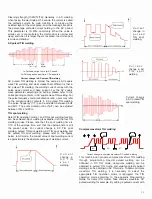
Jasic 315P AC/DC Digital Скачать руководство пользователя страница 12

Control Panel

1—Welding mode selecting zone

It is used to select the welding mode. Press the key in this zone to shift the welding mode among “” (AC square-wave 

TIG), “” (AC pulsed TIG), “” (DC TIG), “” (DC pulsed TIG), “” (AC SMAW) and “” (DC SMAW) with the corresponding 

LED lit. However, if the LED flashes, it indicates that welding is being carried out in the corresponding welding mode 

and that re selection cannot be performed.

2—Parameter and alarm display zone

The digital meter is used for displaying the parameters and error codes, and it also displays the software version when 

starting the machine. The details are as below.
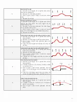
A.

"

Generally,  the  digital  meter  displays  the  pre-set  current,  time,  pulse  duration  ratio  and  frequency  with  the 

corresponding  LED  “A  S  %  Hz”  lit.  Parameters  can  be  adjusted  by  turning  the  knob.  The  digital  meter  displays  the 

welding current during welding, and parameters can be adjusted at this time as well. It displays the parameter being 

adjusted, and turns to display the welding current 3s after the adjustment.

B.

"

Press the key “

” in this zone to shift the display of the digital meter among “A S % Hz”, “V”, “” and “MEMORY” 

with  the  corresponding  LED  lit.  “V”  indicates  the  output  voltage;  “”  is  used  for  selecting  the  operation  mode  of  TIG 

welding 

“MEMORY” can store 5 groups of parameters, and users may perform welding conveniently with these parameters.
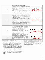
C.

"

The  digital  meter  displays  the  software  version  after  the  machine  is  started,  and  displays  the  pre-set  current  2 

seconds later.

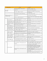
D. In  normal  condition,  all  alarm  LEDs  are  off.  In  case  of  any  error,  the  corresponding  LED  will  illuminate,  and  the 

digital meter will display the corresponding error code.

When  the  “OC”  LED  illuminates  and  the  digital  meter  displays  “E-0”  or  “E-1”,  it  indicates  that  over  current  occurs. 

Restart the machine, and welding can be continued.

When the “LV/OV” LED illuminates and the digital meter displays “E-2”, it indicates that the mains voltage is overly low 

or  that  the  secondary  inverter  drive  power  source  fails.  In  the  former  condition,  welding  can  be  recovered  when  the 

mains voltage goes into normal. In the latter condition, please consult the service department.

When the “OH” LED illuminates and the digital meter displays “E-3” or “E-4”, it indicates that welding is forced to stop 

because the main circuit of the machine is overheated. In this condition, it is unnecessary to turn off the machine, but 

just wait a few minutes, and then welding can be continued.

3—Parameter adjustment knob

It is used to adjust all adjustable parameters.

4—Mains switch

1.  Welding mode selector
2.  Parameter and alarm 

displays

3.  Parameter adjustment 

knob

4.  Mains on off switch
5.  TIG parameter 

selection area

6.  MMA parameter 

selection area

7.  Remote control 

selection

JT-200D panel shown

Содержание 315P AC/DC Digital

Страница 1: ...cleaning width Remote control interface AC function for aluminium and aluminium alloys DC TIG function for carbon steel copper and non ferrous metals Smooth arc and stable welding performance Integrat...

Страница 2: ...Operator Manual www jasic co uk TIG Series TIG 200P AC DC Digital JT 200D TIG 315P AC DC Digital JT 315D...

Страница 3: ...pplier of equipment in the UK and our products are supported by our extensive service network Call your distributor in the unlikely event of a problem occurring Please record below the details from yo...

Страница 4: ...e protection Insulate yourself from work and ground using dry insulating mats or covers big enough to prevent any physical contact with the work ground Never touch the electrode if you are in contact...

Страница 5: ...an may cut fingers and hands and snag garments Protections and coverings may be removed for maintenance and controls only by qualified personnel after first disconnecting the power supply cable Replac...

Страница 6: ...etwork at the public network connection point must be applied to these systems In this case the installer or the user is responsible for ensuring the equipment can be connected consulting the electric...

Страница 7: ...igent digital control so it is not sensitive to the change of parameters of components That is the performance of welding machine will not be a ected by the change of the parameters of certain compone...

Страница 8: ...cation protocol Available as a special order Perfect automatic recording function All data such as cumulative start up times cumulative running time cumulative welding time cumulative TIG welding time...

Страница 9: ...range MMA A DC 10 200 AC 20 200 DC 10 300 AC 20 300 Arc force current range MMA A 0 100 0 100 Initial current range A DC 10 200 AC 20 200 DC 10 320 AC 20 250 Peak current range A DC 10 205 AC 30 205...

Страница 10: ...ch connector 5 Remote control connector 6 Positive power connector 7 Mains switch 8 Adjustment control Front view JT 315D 1 Control panel 2 Negative output socket 3 Torch gas connector 4 Torch switch...

Страница 11: ...Data plate 10 Power cable input 11 Shield gas input connector 12 Serial number Rear View JT 315D 9 Data plate 10 Power cable input 11 Water input connector 12 Shield gas input connector 13 Serial numb...

Страница 12: ...arameters and users may perform welding conveniently with these parameters C The digital meter displays the software version after the machine is started and displays the pre set current 2 seconds lat...

Страница 13: ...least to avoid arc breaking due to overly low current and should not be higher than the pre set current The foot control is e ective only in TIG mode 1 Pre flow time 7 Pilot arc current 2 Initial cur...

Страница 14: ...ilable for this machine Concept hints Parameter group 5 parameter groups 1 5 are available for users to save the welding parameters based on a welding application and all parameters in all the six wel...

Страница 15: ...erally 1 5 3 times the welding current and the arc ignition time is 0 02 0 05s When in low current ignition mode the arc ignition current is generally 0 2 0 5 times the welding current and the arc ign...

Страница 16: ...ng it will lead to a waste of shield gas if it is too short it will result in the oxidation of weld bead and electrode When in AC TIG or for special materials the time should be longer Upslope time tr...

Страница 17: ...between 10 and 90 TIG spot welding Select TIG operation mode 1 and TIG spot welding function can be achieved Spot welding is available in all the four TIG welding modes Please note that the spot weld...

Страница 18: ...de no Operation Torch trigger operation and current curve 0 Follow mode Push the torch trigger arc is ignited and current rises to the pre set value Release it arc stops 1 1T Spot welding mode Push th...

Страница 19: ...again and then turn to If push the torch trigger and release it at once arc will stop 7 Cycle single operation mode with initial current Push the torch trigger arc is ignited and current reaches the i...

Страница 20: ...se it current drops to pilot arc current value Push it again arc stops 13 Double operation 3T mode Push the torch trigger arc is ignited and current rises gradually The torch trigger can be released a...

Страница 21: ...t again current rises to the preset value and then turn to If push the torch trigger and release it at once or release the torch trigger and push it at once arc will stop Note Preset value is the peak...

Страница 22: ...connected to the negative terminal and the work return to the positive terminal MMA welding DC Insert the cable plug with electrode holder into the socket on the front panel of the welding machine and...

Страница 23: ...ding to the relevant content in this manual and TIG welding can be carried out The arc ignition mode of this machine is non contact arc ignition During welding the parameter display meter displays the...

Страница 24: ...o before opening the case NOTE When the inverter welder is powered on defective components may explode or lead to explosion of other components Wear face guard and long sleeved clothing when maintain...

Страница 25: ...th a higher rated current holder MMA Arc is easy to break Arc breaking voltage is too low Increase the arc breaking voltage TIG There is no current output when pushing the torch trigger Welding can be...

Страница 26: ...o the power cord which is connected to other electric appliances of serious interference Other malfunction Other malfunction Contact the service centre Type Alarm Automatic response Cause Solution Ove...

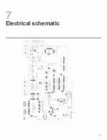
Страница 27: ...Electrical schematic 7 25...

Страница 28: ...Parts list 8 JT 200D 26...

Страница 29: ...0040578 Top board 15 10022057 Fan 32 10038699 Central board 16 10016389 Connector for water 33 10020826 Power line 17 10021912 Line button 27 No Part no Description No Part no Description 1 10014869 F...

Страница 30: ...JT 315D 28...

Страница 31: ...JT 200D JT 315D DIGITAL AC DC PULSE TIG MMA WELDING MACHINE Order code JT 200D JT 315D Wilkinson Star Limited Issue 1 January 2014 Product is subject to change without notice xxix...

Страница 32: ...rigger and release it at once Release the torch trigger and push it at once Push the torch trigger twice within 0 5s or Release the torch trigger twice within 0 5s or These are the general description...

Страница 33: ...ration stipulations 100 codes are classified and explained in Attached Table 2 based on their functions and characteristics and users should fully understand all those For welding machine operation mo...

Страница 34: ...s 100 kinds of operation codes are available for this machine there is more than one code sequence to achieve the specific operation function and users only need to choose one of them It should be str...

Страница 35: ...ode with initial current 8 Inner timing operation mode 9 Outer timing operation mode 10 Cycle double operation mode without initial current 11 Cycle double operation mode with initial current 12 Singl...

Страница 36: ...quartic operation stop arc 9X Immediate transfer code X 0 Turn to next step X 0 Turn to Step X X 0 9 The definition of order X The definition of order X The definition of order X The definition of or...

Страница 37: ...d you can press the parameter display selecting key and the operation mode LED flashes This means you have entered into code editing state Code no selecting and code content editing After you enter in...

Отзывы: