23
3.4
CABLE CONNECTION
Remove the cover from the rear bottom of the receiver, and connect the antenna cable, power cable,
and all other necessary cables to the terminal board. All cables can be connected using either a
Phillips or flap-tip screwdriver.
3.4.1
Connecting the antenna cable
Connect the antenna cable to the appropriate antenna terminal on the terminal board.
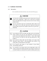
CAUTION
When connecting the antenna cable to the terminal board, be careful not to
connect the conductor wire and the shield wire to the wrong terminals.
Incorrect wiring may cause equipment and/or antenna trouble or deterioration
of the receiver signal.
Direct-current power is supplied to the antenna cable. Be careful not to short-
circuit the conductor wire and the shield wire. Short-circuiting could lead to
equipment and/or antenna failures or deterioration of the signal to the receiver.
If a ground-meter or a ground-lamp is connected to the DC power of the vessel,
do not connect the shield wire of the antenna cable to the frame grounding
terminal on the vessel. DC power to the antenna cable may cause the
ground-meter to deflect or the ground-lamp to light up.
♦
Recommended cable:
Armored 50-ohm coaxial cable
Model RG-10U/Y or equivalent
Procedure
(1) Loosen the screw of the antenna cable input terminal on the terminal board.
(2) Pass the cable through the gaskets.
(3) Insert the conductor of the cable into the first hole from the left of the terminal board, and the
shield wire into the second hole.
(4) Tighten the screw to fix the cable.
Содержание NCR-330
Страница 1: ...NCR 330 NAVTEX RECEIVER INSTRUCTION MANUAL...
Страница 7: ...vi EXTERNAL VIEW OF EQUIPMENT...
Страница 14: ...3 1 4 STRUCTURE Unit mm External diagram of the NCR 330 NAVTEX Receiver...
Страница 15: ...4 External diagram of the NAW 330 NAVTEX Antenna approx 610 approx 4 5 approx 190 approx 400 MAST 30 90...
Страница 16: ...5 1 5 OVERALL FLOW CHART DIAGRAM Overall Flow Chart Diagram of the NCR 330 NAVTEX Receiver...
Страница 17: ...6 Overall Flow Chart Diagram of the NAW 330 NAVTEX Antenna...
Страница 21: ...10 2 2 REAR PANEL View of the equipment with rear cover removed...
Страница 23: ...12...
Страница 31: ...20 Fig 3 5 2 Wiring the rear terminal board Only when the power unit is to be used...
Страница 33: ...22 Fig 3 6 2 Wiring the rear terminal board Only when battery power is to be used...
Страница 66: ...55 Fig 6 3 Removing the casing...
Страница 72: ...61...


