19
3.3
EQUIPMENT COMPONENT CONNECTION
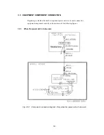
Depending on whether the built-in or optional power unit is to be used, connect the
equipment components correctly as shown in one of the following figures:
3.3.1
When the power unit is to be used
Fig. 3-5-1 Component connection diagram - Only when the power unit is to be used
Содержание NCR-330
Страница 1: ...NCR 330 NAVTEX RECEIVER INSTRUCTION MANUAL...
Страница 7: ...vi EXTERNAL VIEW OF EQUIPMENT...
Страница 14: ...3 1 4 STRUCTURE Unit mm External diagram of the NCR 330 NAVTEX Receiver...
Страница 15: ...4 External diagram of the NAW 330 NAVTEX Antenna approx 610 approx 4 5 approx 190 approx 400 MAST 30 90...
Страница 16: ...5 1 5 OVERALL FLOW CHART DIAGRAM Overall Flow Chart Diagram of the NCR 330 NAVTEX Receiver...
Страница 17: ...6 Overall Flow Chart Diagram of the NAW 330 NAVTEX Antenna...
Страница 21: ...10 2 2 REAR PANEL View of the equipment with rear cover removed...
Страница 23: ...12...
Страница 31: ...20 Fig 3 5 2 Wiring the rear terminal board Only when the power unit is to be used...
Страница 33: ...22 Fig 3 6 2 Wiring the rear terminal board Only when battery power is to be used...
Страница 66: ...55 Fig 6 3 Removing the casing...
Страница 72: ...61...


