background image

10

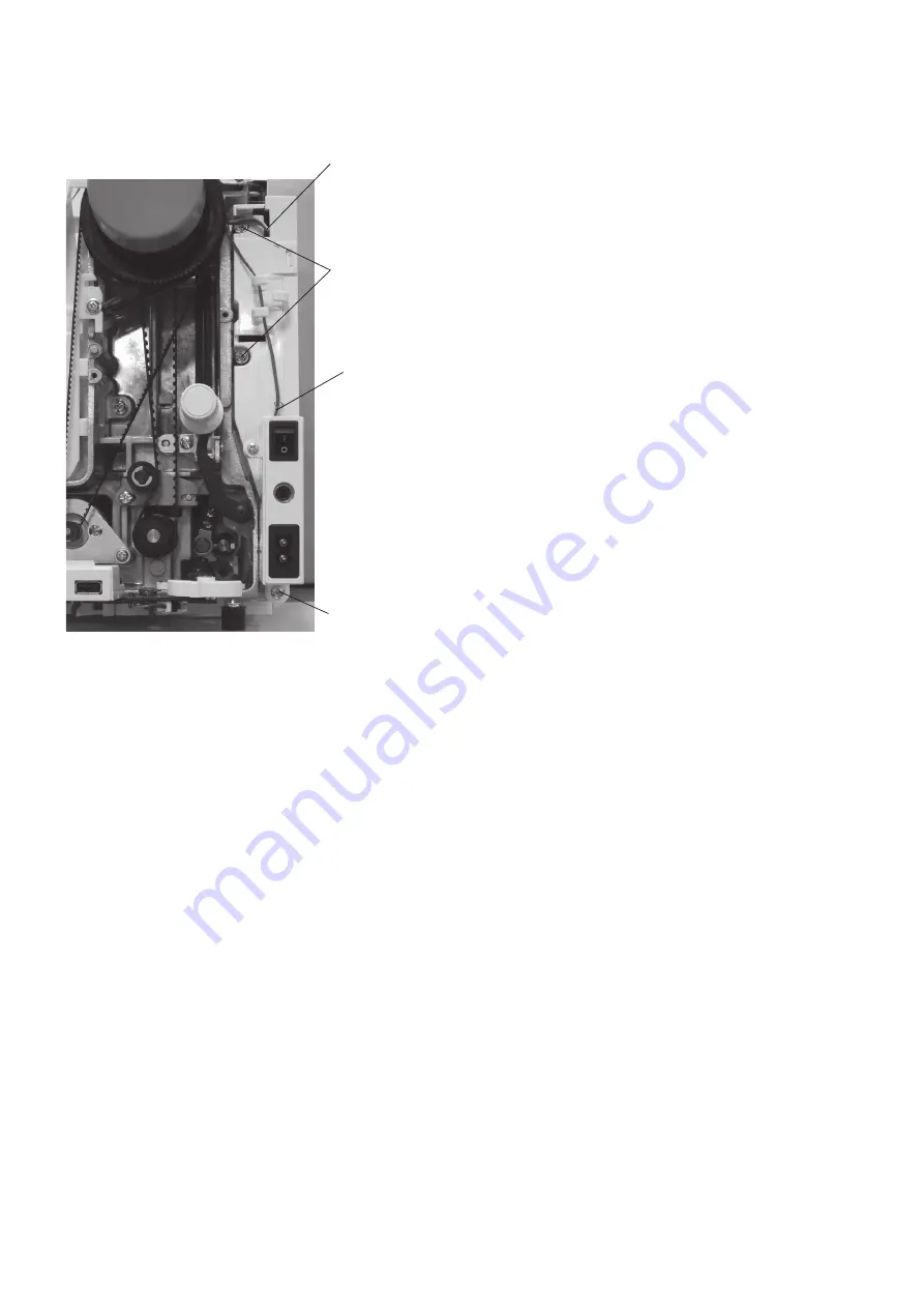
Switching power supply unit

To remove:

1.  Remove the belt cover, the top cover and the front    

  cover (refer to pages 1, 2 and 5).
2.  Disconnect the switching power supply connector 

  from the switching power supply unit.

3.  Remove the foot control connector from the printed    

  circuit board A (refer to page 8).

4.  Remove the setscrews, and switching power supply.

To attach:

Follow the above procedure in reverse.

Replacing electronic components

Switching power supply connector

Setscrew

Foot control 

connector (cord)

Setscrew

Содержание SKYLINE S6

Страница 1: ...SERVICE MANUAL MODEL SKYLINE S6 First Edition 12 December 2018...

Страница 2: ...ension unit 12 Mechanical adjustment Feed dog height 13 Needle drop position 14 Presser bar height 15 Hook timing 16 Needle bar height 17 Clearance between needle and tip of the rotary hook 18 19 Pres...

Страница 3: ...w A Belt cover To remove 1 Remove the cap and setscrew B 2 Remove the setscrew C 3 Loosen the two setscrews D 4 Pull the rear side of the belt cover to disengage it from the rear cover 5 Remove the be...

Страница 4: ...the top cover and raise the carrying handle Pull the top cover toward you to remove it To attach Follow the above procedure in reverse To attach the flange plate put the flange plate on to the bobbin...

Страница 5: ...ve procedure in reverse Base cover To remove 1 Remove the setscrews B 2 Remove the base cover To attach Follow the above procedure in reverse Bed cover To remove 1 Remove the setscrews C 2 Remove the...

Страница 6: ...the left 4 Pull out the free arm cover forcedly to the left while pulling open the front side to disengage the hook B and remove the free arm cover To attach 1 Place the free arm cover on the free ar...

Страница 7: ...the setscrew C behind the face cover 5 Loosen the setscrew D inside of the machine body 6 Unlock the hooks from the front cover 7 While pushing the rear cover through the hole A with a screwdriver rem...

Страница 8: ...r refer to pages 1 to 3 2 Loosen the setscrew A 3 Loosen the setscrew B 4 Remove the four setscrews C 5 Push the rear cover from the holes D and E with a screwdriver to remove the hook of rear cover 6...

Страница 9: ...rs the needle eye 2 If the threader hook is not aligned vertically with the needle eye loosen the setscrew A Adjust the stopper position so that the hook enters into the needle eye Tighten the setscre...

Страница 10: ...nted circuit board A adjust the following items Knee Lifter refer to page 37 Presser bar height refer to page 29 Embroidery foot height refer to page 35 Board A schematic Setscrew Setscrew Slide volum...

Страница 11: ...rd A refer to page 8 3 Remove the CS rings 4 Remove the setscrews and the printed circuit board F To attach Follow the above procedure in reverse Speed control slider To remove 1 Remove the front cove...

Страница 12: ...ower supply connector from the switching power supply unit 3 Remove the foot control connector from the printed circuit board A refer to page 8 4 Remove the setscrews and switching power supply To att...

Страница 13: ...the motor belt 4 Remove the setscrews 2 pcs and the DC motor To attach 1 Attach the DC motor and slightly tighten the setscrews 2 Attach the motor belt and adjust the belt tension Push the middle of...

Страница 14: ...emove the belt cover and the top cover refer to page 1 and 2 2 Remove the front cover refer to page 5 3 Disconnect the thread tension motor connector from the printed circuit board A refer to page 8 4...

Страница 15: ...Loosen the setscrew A 6 Loosen the nut with a socket wrench Turn the adjusting screw and adjust the feed dog hight to 0 85 mm 7 Tighten the nut and setscrew A 8 Turn the handwheel and check that the f...

Страница 16: ...be 0 2 mm or more 1 Attach the 14 needle Turn the power switch ON and select straight stitch 1 2 Check the clearance between the needle and the side of the needle hole when the needle drop position is...

Страница 17: ...oot A Slot Setscrew To adjust 1 Attach the zigzag foot A 2 Drop the feed dogs 3 Raise the presser foot with the presser foot lifter 4 Open the face cover Loosen the setscrew on the presser bar support...

Страница 18: ...turn the switch OFF 4 Remove the presser foot the needle plate and the bobbin holder 5 Turn the handwheel toward you to lower the needle at its lowest position 6 Loosen the setscrews A use an Allen wr...

Страница 19: ...e needle bar height Tighten the hexagonal socket screw Be careful not to turn the needle bar 7 Attach the bobbin holder and the needle plate Hexagonal socket screw Needle setting groove Needle bar Nee...
Страница 20: ...factory setting mode Press Bobbin key The machine will set the zigzag width at maximum 6 Turn the handwheel toward you until the tip of the hook comes behind the test pin 7 Loosen the hexagonal socke...

Страница 21: ...ghten the setscrew C lightly 3 Turn the handwheel toward you until the tip of the hook comes behind the test pin Adjust the clearance between the needle and the tip of the rotary hook by moving the ho...

Страница 22: ...t normal up position the The presser foot symbol appears When the presser bar is at lowered position the presser foot symbol disappears If not follow the procedure below To adjust 1 Remove the top cov...

Страница 23: ...plate 3 Turn the handwheel toward you so the tip of the rotary hook is within the width of feed dog as shown Check the rotary play of the hook 4 If the backlash is too much or too little loosen the he...

Страница 24: ...til PH changes to q to w on LCD 5 The needle height should be 7 2 to 8 2 mm above from the surface of the needle plate If not adjust the upper shaft shield position To adjust 1 Remove the top cover 2...

Страница 25: ...50 at the speed of 110 mm sec with the tension at AUTO Be sure the presser foot is lowered 1 Set the thread tension dial to AUTO 2 Open the face cover Adjust the tension by turning the thread tension...

Страница 26: ...ight so the Buttonhole lever slightly touches to the Buttonhole foot Tighten the setscrew To check 1 While pressing the needle up down and aut lock stitch buttons turn the power switch on The LCD disp...

Страница 27: ...alized and moving cutter moves to its home position automatically 3 The distance between the end of moving cutter and the end of thread cutter plate slit should be 0 7 to 1 5 mm If not adjust it as fo...

Страница 28: ...urn the power switch on The LCD display Press 4 key to enter the solenoid test mode 3 Press the needle up down button to release the thread tension The LCD will display on Make sure the needle thread...

Страница 29: ...e needle up down button twice to raise the needle and the upper feed dog position will be initialized 4 Check if the clearance between the connecting link and upper feed lower shaft is 2 5 mm If not a...

Страница 30: ...Remove the top cover refer to page 2 2 Loosen the hexagonal socket screws on upper feed upper shaft rear arm use an Allen wrench of 2 mm width across flats 3 Insert the 4 mm spacer between the upper...

Страница 31: ...nitialized 4 Press the presser foot lifter button to lower the presser foot Turn the power switch off 5 Raise the toe of the dual feed foot and leave it as it is 6 Turn the handwheel toward you to low...

Страница 32: ...sting screw D comes to the adjusting position Turn the adjusting screw in the direction of A if the measurement is more than 39 mm Turn the adjusting screw in the direction of B if the measurement is...

Страница 33: ...setscrew TP and move the base plate up or down to adjust it Tighten the setscrew TP firmly after the adjustment The actuator of the micro switch should be aligned with the needle plate sensor knob as...

Страница 34: ...t S symbol appears and blinks when the needle plate is attached 3 Replace the needle plate with the needle plate for straight stitch Be sure that S symbol and number 3 appears If not adjust the micro...

Страница 35: ...ces clearance upper and clearance lower between the knee lifter lever 1 and presser bar lifter Be sure that the knee lifter shaft and the knee lifter lever 1 engage smoothly without play Turn the adju...

Страница 36: ...iagnosis test Check or replace the following part s if nothing happens when the power switch is turned on 1 Be sure that the machine is plugged in 2 Be sure that the connectors are connected to the pr...

Страница 37: ...en button 2 is pressed LCD displays F3 when button 3 is pressed LCD displays 03 and BH When the buttonhole lever is pulled buzzer sounds and LCD displays BH symbol BH symbol Bobbin symbol Press button...

Страница 38: ...ghest position feed phase Press the needle up down button If the result is correct condition press the start stop button to proceed the next step If the result is defective condition press the reverse...

Страница 39: ...ume from left to right then return to the left If the result is correct condition press the start stop button to proceed the next step If the result is defective condition press the reverse stitch but...

Страница 40: ...feed dog symbol When the drop feed lever is shifted away from you LCD displays as Fig 1 When the drop feed lever is shifted toward you LCD displays as Fig 2 Fig 1 Feed dog symbol Fig 2 Buzzer does no...

Страница 41: ...d circuit board A Buzzer sounds after few seconds when the self diagnostic test has been finished The test result has been determined CORRECT Buzzer sounds and LCD displays 00 DEFECTIVE Caution buzzer...

Отзывы: