Setup
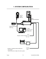
Desktop Robot JR3000
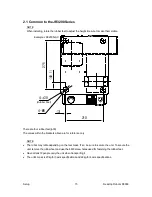
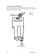
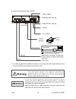
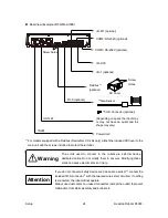
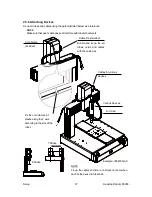
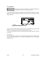
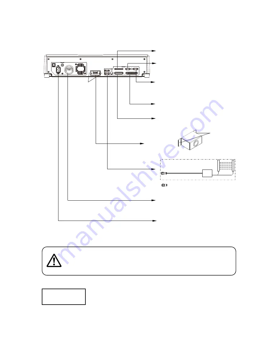
Rear View (Example: JR3403N-AC/BC)
*
1
For models equipped with a Fieldbus (DeviceNet, CC-Link only), attach the included FB Cover to the
main unit with the screws included to protect the terminal.
If you do not connect a safety device such as an area sensor*
2
, connect the
included I/O-S connector*
3
with the two lead wires short circuited.. If nothing
is connected, the robot will not operate.
Always use dust covers on unused connectors (except the outlet) to prevent
malfunction from static electricity and/or dust etc.
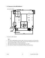
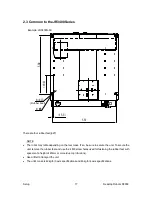
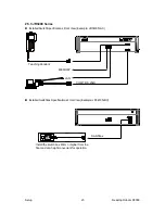
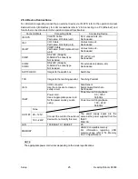
COM3: RS-232C (optional)
COM2: RS-232C (optional)
I/O-1 (optional)
I/O-SYS
I/O-S (optional)
OUTLET
INLET
Power Cord
*
3
I/O-S Connector (optional)
I/O-MT (optional)
Fieldbus *
1
(optional)
*
2
Area Sensor
(Depending on specs the robot may
or may not have an outlet and the
shape may vary)
Screw Holes
FB Cover
Screw
Holes
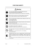
Warning
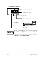
The cords used to connect to the outlets are external device
dedicated cords. Do not modify them in any way. Modifying these
cords can cause electric shock or injury.
Attention
24


