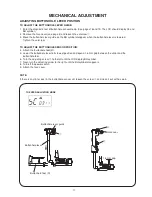
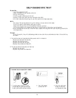
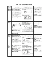
background image

16

X

Threader plate
 supporter

Threader 

positioning 

plate

FIG. 3

Pin

Adjustment of left or right direction

Threader plate

Nut

w

View from "X"

q

Vertical adjustment

FIG. 2

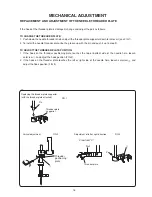
REPlACEMENT AND ADjusTMENT OF THE NEEDlE THREADER PlATE

If the hook of the threader plate is damaged, change and adjust the part as follows:

TO CHANgE THE THREADER PlATE:
1.  Push down the needle threader knob and pull the threader plate supporter down to remove it (see FIG 1).
2.  To install the needle threader plate, line the groove up with the pin and push it up to snap fit.

TO ADjusT THE THREADER PlATE POsiTiON:
1.  If the hook on the threader positioning plate touches the top or bottom side of the needle hole, loosen 

setscrew 

q

 and adjust the hook position (FIG.2).

2.  If the hook on the threader plate touches the left or right side of the needle hole, loosen setscrew 

w

 and 

adjust the hook position (FIG 3).

Replacing the threader plate supporter
(with the threader plate attached)

FIG. 1

MECHANiCAl ADjusTMENT

Содержание 5030

Страница 1: ...SERVICE MANUAL MODEL 5030 81030DC 5050 81050DC 5100 81100DC N 2000 DC3100...

Страница 2: ...EED DOG HEIGHT 13 TOP TENSION 14 STRETCH STITCH FEED BALANCE 15 REPLACEMENT AND ADJUSTMENT OF THE NEEDLE THREADER PLATE 16 ADJUSTING BUTTONHOLE LEVER POSITION 17 SELF DIAGNOSTIC TEST SELF DIAGNOSTIC T...

Страница 3: ...le and thread Use a HA x 11 blue tip needle See mechanical adjustment Needle bar height See mechanical adjustment Adjustment of hook timing See mechanical adjustment Clearance between needle and tip o...

Страница 4: ...bbin thread 1 Bobbin holder is incorrectly threaded 2 Too much thread is wound on the bobbin 3 Lint is stuck inside the bobbin holder 4 Thread quality is too low 5 Thread is jamming around the bobbin...

Страница 5: ...t tension 4 Not enough oil 5 Upper shaft gear is loose Eliminate the backlash Eliminate the looseness See part removal and replacement driving motor DC motor Oil all moving parts Eliminate the loosene...

Страница 6: ...ng External Parts FACE COVER To remove 1 Remove the cap and setscrew q and lift the face cover to disengage the rib on the inside Remove the face cover w To attach 2 Follow the above procedures in rev...

Страница 7: ...5 FREE ARM COVER To remove 1 Remove the setscrew q and w Move the free arm cover e to the left Remove the free arm cover To attach Follow the above procedures in reverse Changing External Parts q w e...

Страница 8: ...he setscrews r 2 pcs 5 Loosen the setscrew t 6 Disengage the front cover and rear cover hooks 7 Remove the front cover 8 Disconnect all the connectors from the circuit board A NOTE Do not disconnect t...

Страница 9: ...e page 4 and 5 2 Remove the setscrews q 2 pcs and the setscrews w 3 pcs 3 Remove the setscrews e 4 pcs and back cover r 4 Remove the setscrews t 2 pcs 6 Disengage the front cover and rear cover hooks...

Страница 10: ...d dog below the needle plate Place a block 6 mm thick under the presser foot and lower the presser foot lifter w 3 Loosen the setscrew q Raise the presser foot lifter and tighten the setscrew q firmly...

Страница 11: ...ance between the needle and the edge of the needle hole should be at least 0 2 mm on either side If not adjust as follows 1 Turn the power switch off Remove the face cover See page 4 2 Loosen the hexa...

Страница 12: ...handwheel toward you to lower the needle at its lowest position 5 Loosen the hexagonal socket screw w 2 pcs 6 Move the needle bar 3 4 mm from the lowest position 7 Turn the lower shaft gear until the...

Страница 13: ...ch on 3 Select the pattern left position Set the zigzag width at 0 4 Turn the handwheel toward you until the tip of hook meets the right side of the needle 5 Loosen the hexagonal socket screw q 6 Move...

Страница 14: ...te up or down to within 0 1 to 0 05 mm at the left and right needle position 5 Tighten the setscrews q 2 pcs 6 Attach the face cover Remove the master needle Attach the bobbin holder and needle pate 7...

Страница 15: ...hest position 3 Remove the free arm cover See page 5 4 Loosen the setscrew q and nut w 5 Adjust the feed dog height by turning the adjusting screw e The highest position of the feed dog should be betw...

Страница 16: ...st as follows 1 Set the tension dial 4 2 Remove the face cover and front cover See page 4 and 6 3 Lower the presser foot If the top tension is too loose turn the lead screw in the direction A If the t...

Страница 17: ...to the left to loosen it Move the gear up A or down B to adjust the feed Do not move the gear right or left when adjusting Start the machine and check the movement of the fabric Adjust the hexagonal...

Страница 18: ...he threader plate supporter down to remove it see FIG 1 2 To install the needle threader plate line the groove up with the pin and push it up to snap fit TO ADJUST THE THREADER PLATE POSITION 1 If the...

Страница 19: ...ver is lowered Tighten the setscrew To adjust the buttonhole sensor position 4 Attach the buttonhole foot R 5 Lower the buttonhole lever to its lowest position and open a 1 6 mm gap between the slider...

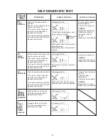
Страница 20: ...est you want to perform Enter self diagnostic mode then select the step number of the diagnostic test you require by pressing the start stop button To begin Turn on the switch If any of the following...

Страница 21: ...S9 when button 5 is pressed LCD displays SC 03 When the buttonhole lever is pulled buzzer sounds and LCD displays BH symbol BH symbol Bobbin symbol Press buttons 1 5 If the result is correct conditio...

Страница 22: ...ard you Lower the needle bar its highest to position zigzag phase Press the needle up down button Raise the needle bar from its lowest position to its highest position feed phase Press the needle up d...

Страница 23: ...is correct condition press the start stop button to proceed the next step If the result is defective condition press the reverse stitch button to proceed the next step The foot control symbol appears...

Страница 24: ...ndition If the result is correct condition press the start stop button to proceed the next step If the result is defective condition press the reverse stitch button to proceed the next step LCD displa...

Страница 25: ...defective part number See pages 19 22 Steps and items section Press the reverse stitch button to return to 01 Turn the power switch off when the self diagnostic test is finished To display the versio...

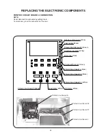
Страница 26: ...circuit board A Printed circuit board F1 Printed circuit board F2 Printed circuit board L Bobbin winding switch Blue Foot control Black Presser foot lifter switch Green Switching regulator White BH se...

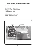
Страница 27: ...rinted circuit board A 3 Remove the screws 4 pcs and the printed circuit board A To attach 1 Follow the above procedures in reverse NOTE Do not disconnect the connectors by pulling on cord To disconne...

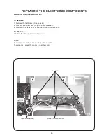
Страница 28: ...2 Pull out connectors from the printed circuit board A 3 Remove the screws 3 pcs and the printed circuit board F2 To attach 1 Follow the above procedures in reverse NOTE Do not disconnect the connecto...

Страница 29: ...ll out connectors from the printed circuit board A 3 Remove the screws 2 pcs and LED cover 4 Remove the printed circuit board F2 To attach 1 Follow the above procedures in reverse NOTE Do not disconne...

Страница 30: ...d circuit board A 3 Remove the screw and LED cover 4 Remove the printed circuit board L To attach 1 Follow the above procedures in reverse NOTE Do not disconnect the connectors by pulling on cord To d...

Страница 31: ...hten them with setscrews q 2 pcs lightly 2 Move the motor up or down to adjust the motor belt tension The belt should deflect 5 mm when applying 200 grams of load to the middle of the belt Tighten the...

Страница 32: ...ont cover and the rear cover See pages 6 and 7 2 Remove the setscrews q 3 pcs and the switching regulator 3 Remove the setscrews w 4 pcs To attach 4 Follow the above procedures in reverse Replacing th...

Отзывы: