JPC70
www.janitza.com
12
5.
Assembly
5. 1
Installation location
The device is suitable for indoor installation
in a stationary and weather-protected switch
board.
Ensure that grounding is provided for
switchboards.
5. 2
Installation position
The cut-out size in the switchboard is
186
+0.8
mm x 129
+0.8
mm with a wall thickness
of 2 to 6 mm.
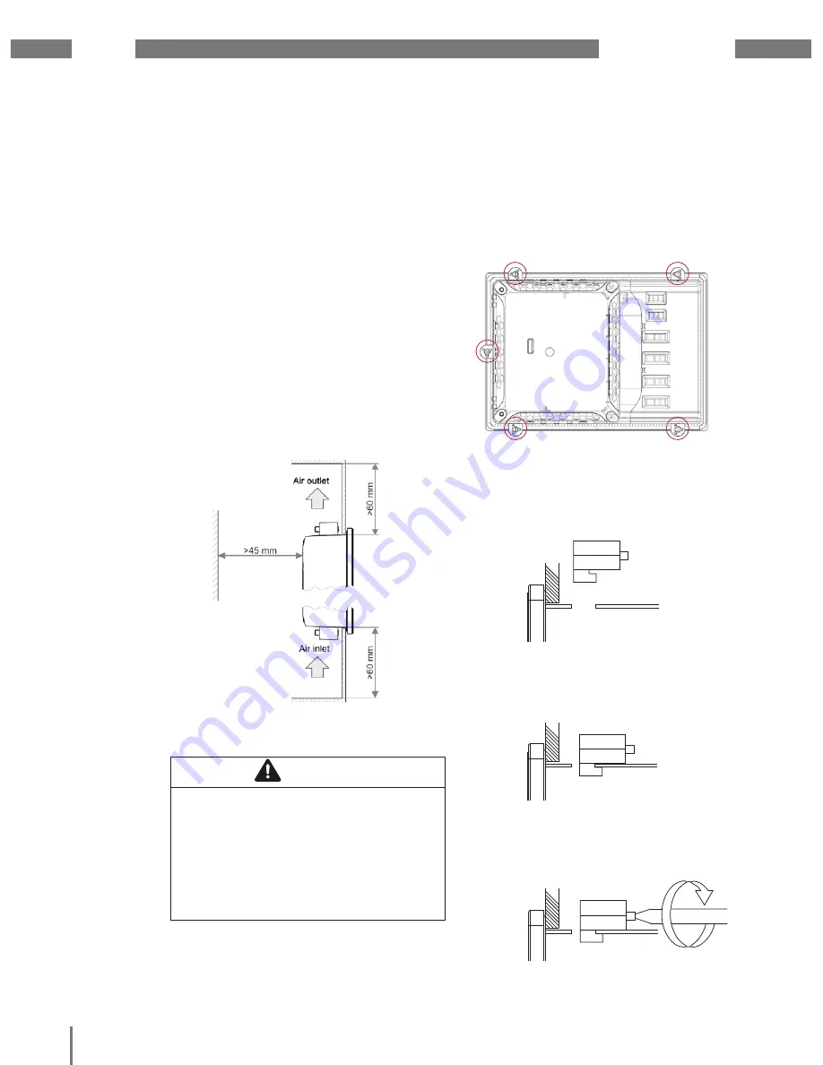
In order to achieve adequate ventilation,
the following must be observed:
• Install the device vertically.
• Observe a minimum clearance of 60 mm
above and below.
• Observe a minimum clearance of 40 mm
to the sides.
Fig. 3: Installation position of the JPC70
5. 3
Fastening
The device must be installed using the
supplied retaining clamps (see Fig. 6)
on a level, clean and burr-free surface.
Unevenness can cause damage to the
display and result in the penetration of dust
and water.
Fig. 4: Rear view with retaining clamps
1. Insert the front side of the device in the
provided installation cut-out.
2. Insert the retaining clamps in the
recesses provided on the device.
Fig. 5: Inserting the retaining clamps
3. Slide the retaining clamps towards the
rear until they are flush with the back side
of the recess.
Fig. 6: Sliding the retaining clamps towards the rear
4. Fix the retaining clamps by tightening the
fastening screws on the wall and/or the
switch cabinet sheet metal.
Fig. 7: Fixing the retaining clamps
CAUTION
Property damage due to noncompliance
with the assembly instructions!
Noncompliance with the assembly
instructions can result in damage or
destruction of your device.
Observe the specifications for the
installation position in the sections
"Assembly" and "Technical data".


