background image

 Janitza AHF 

4

Contents

1.  Information on the device and the user manual   


6

1. 1 

Disclaimer 

      6

1. 2 

Copyright 

notice 

     6

1. 3 

Technical 

changes 

     6

1. 4 

Defective 

device/disposal 

    6

2.  Safety        7

2. 1 

Symbols 

used 

      7

2. 2 

Safety 

measures 

     8

2. 3 

Electrically 

qualified 

personnel 

    8

2. 4 

Intended 

use 

      8

2. 5 

Warranty in the event of damage  


8

2. 6 

Information on setting up the device 


9

2. 7 

Information 

on 

storage 

     9

2. 8 

Standards 

      10

3.  Scope 

of 

delivery 


11

3. 1 

Accessories 

(optional) 

     11

4.  Product 

description 

      12

4. 1 

Device 

description 

     12

4. 2 

Type 

designation 

     12

4. 3 

Product 

features 

     13

4. 4 

Dimensional 

drawings 

     14

4. 5 

Operating 

principle 

     16

5.  Installation and power connection 


18

5. 1 

Before 

installation 

     18

5. 2 

Electrical 

connection 

     21

5. 2. 1  Closed 

loop 

      21

5. 2. 2  Open 

loop 


      22

5. 2. 3  Electrical connection of an AHF single module 


23

5. 2. 4  Location of the current and signal interfaces 


24

5. 3 

Electrical connection of more than one module with LCD display 

27

5. 3. 1  Electrical connection of modules with LCD display  

with 

different 

capacities 

     29

5. 4 

Electrical connection of several modules without display 


30

5. 4. 1  Electrical connection of the AHF R 400 V 50 A AHF 


30

5. 4. 2  Electrical connection of modules without display with  

different 

capacities 

     32

5. 5 

Installation of the current transformers 


33

5. 5. 1  Current 

transformer 

selection 

    34

5. 5. 2  CT installation on the load side (open loop) 


35

5. 5. 3  CT installation on the grid side (closed loop) 


37

5. 5. 4  Connection of an AHF to a Janitza UMG    


40

Содержание Active Harmonics Filter

Страница 1: ...100 024 1d 07 2019 Janitza electronics GmbH Vor dem Polst ck 6 D 35633 Lahnau Phone support 49 6441 9642 22 Email info janitza de www janitza de www janitza de Janitza AHF Active Harmonics Filter Use...

Страница 2: ...TER Doc no 2 100 024 1d Date 07 2019 Subject to technical changes The contents of our documentation have been compiled with great care and reflect the current state of the information available to us...

Страница 3: ...Janitza AHF 3 The settings in the Parameter Settings menu are password protected see section 8 1 3 Please cut out this section and keep it in a safe place User password 080808...

Страница 4: ...power connection 18 5 1 Before installation 18 5 2 Electrical connection 21 5 2 1 Closed loop 21 5 2 2 Open loop 22 5 2 3 Electrical connection of an AHF single module 23 5 2 4 Location of the curren...

Страница 5: ...8 1 3 The Parameters button 50 8 1 4 The Measurement button 56 8 2 System operation with more than one module with display 62 8 3 Monitoring and troubleshooting of modules without display 63 8 3 1 7...

Страница 6: ...iated with the product available for the entire service life and pass them on to any possible subsequent users Find out about device revisions and the associated modifications of the documentation ass...

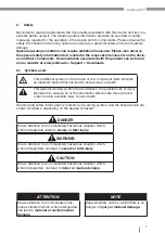
Страница 7: ...es an electrical hazard that can lead to severe injury or death This general warning symbol draws attention to a possible risk of injury Be certain to observe all of the information listed under this...

Страница 8: ...ed for installation in vehicles Use of the devices and their components in non stationary equipment constitutes an exceptional environmental condition and is only permissible by special agreement not...

Страница 9: ...risk of fire or electric shock Ground the device When installing wiring bear the compensation capacity and the current carrying capac ity in mind Ensure that there is no corrosive gas or electrically...

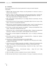
Страница 10: ...ent Tech niques Electrostatic Discharge Immunity Test 7 IEC 61000 4 3 2011 4 Electromagnetic compatibility EMC Testing and measurement techniques Radiated radio frequency electromagnetic field immunit...

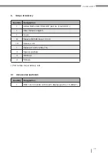
Страница 11: ...rt no 14 200 XX 1 1 User manual english 1 Cover 6 Resistor B2508 blue 2 5 mm 10 Screw 4 x 8 1 Resistor 1 4W 120 1 4 Spacer washers 4 Washers 4 Screws 1 Part number as per delivery note Quantity Design...

Страница 12: ...with N conductor and by automatic mains frequency detection The compensation strategy can be modified during ongoing operation The configurable standby operation in dependence on the voltage distortio...

Страница 13: ...0 cos 1 0 Compensation strategy can be modified during ongoing operation Freely configurable compensation rate for each individual harmonic even and odd numbered Modular system for easy adaptation to...

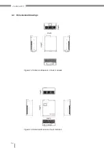
Страница 14: ...Janitza AHF 14 Figure 2 2 External dimension of rack modules Figure 2 3 External dimension of wall modules Depth Height Width Depth Width Height 4 4 Dimensional drawings...

Страница 15: ...50 A 500 557 286 AHF LCD R 400 V 25 A 440 490 150 AHF LCD R 400 V 35 A 440 490 150 AHF LCD R 400 V 50 A 440 590 190 AHF LCD R 400 V 60 A 440 590 190 AHF LCD R 400 V 75 A 440 625 234 AHF LCD R 400 V 10...

Страница 16: ...se of the AHF reduces grid distortions Reduction of the harmonics load Reduction of outage costs e g for frequency converters Automatic detection of resonance points Individual compensation and dynami...

Страница 17: ...d point O VAO is Vdc 2 When Sa2 Sa3 are switched on and Sa1 Sa4 are switched off point A is connected to point O so that VAO is equal to 0 When Sa3 Sa4 are switched on and Sa1 Sa2 are switched off VAO...

Страница 18: ...dule The wall module must be fastened to a solid wall whereby the specified size and location of the drilled holes for the installation are shown in Figure 3 2 Connection options ATTENTION Material da...

Страница 19: ...wire connection if present Do not touching bare or stripped leads that are energized Equip stranded conductors with wire ferrules Hazardous voltages can be present in all circuitry parts that are con...

Страница 20: ...nstallation drawing for the Janitza AHF LCD W 400 V 50 rack module Post Housing plate Drilled hole Figure 3 2 Specified size and installation drawing for the Janitza AHF LCD W 400 V 50 A wall module D...

Страница 21: ...lter module is installed use of the open loop connection version is man datory If this is not possible summation current transformers must be employed see the section Closed Loop 5 2 1 Closed loop 1S1...

Страница 22: ...Figure 3 4b Open loop Load side Grid side If the converter is connected using the closed loop version with only one filter module the Network function must be enabled when selecting the converter on t...

Страница 23: ...ase conductor system with N conductor Input A phase L1 input terminal Input B phase L2 input terminal Input C phase L3 input terminal N neutral conductor terminal PE ground wire Note Because the housi...

Страница 24: ...ork interface and interface for potential free contact 5 2 4 Location of the current and signal interfaces The central 7 inch monitor is connected to the monitoring interface via the communication cab...

Страница 25: ...PO button if there is no connection to the central monitor 10 485 RS 485 signal Connection between modules and monitoring system 11 485 RS 485 signal Connection between modules and monitoring system 1...

Страница 26: ...n of the DIP switch and the module numbers The assignments for the network interface and the interface for the potential free contact are indicated in Figure 3 7 and Table 3 3 The potential free conta...

Страница 27: ...g of the individual modules is omitted When using several modules the connection is carried out the same as for a single module In this case only the open loop connection version is permissible If no...

Страница 28: ...1 2S2 3S1 3S2 CT A A N B B N C C N AHF A B C N PE A A N B B N C C N A B C N PE AHF Figure 3 12 Electrical connection of two LCD modules Electrical connection of more than one LCD module 1 N A L1 B L2...

Страница 29: ...W 400 V 25 A and the AHF LCD W 400 V 50 A can be combined with each other With this combination the electrical connection of the power terminals must be carried out according to section 5 3 important...

Страница 30: ...ting a signal interface for the modules without a display Connect the CT signal interface as well as 485 485 EPO_A and GND_ISO Example Three AHF R 400 V 50 A modules arranged in parallel Filter module...

Страница 31: ...Janitza AHF 31 Figure 3 17 Signal interface connection for three modules Signal interface of module 1 Signal interface of module 3 Signal interface of module 2...

Страница 32: ...sation of harmonics current with different capacities is accomplished using several modules without a display Installation is done in the same manner for these modules as for the previously described...

Страница 33: ...ly short circuit the secondary lines of the current transformers to the Test status Check the test switch short circuiting connection beforehand Only use current transformers with basic insulation to...

Страница 34: ...unt when selecting the CT ratio A selection of 1 5 times the maximum current in operation is recommended to ensure more accurate harmonic compensation whereby a resonable tolerance is also recommended...

Страница 35: ...Figure 3 20 Current transformer connection on the load side single line representation 5 5 2 CT installation on the load side open loop After the installation of the CT on the load side the signal is...

Страница 36: ...dditional compensation Figure 3 21 c Current transformer connection on the load side with additional compensation com pensation before the AHF connections for current transformer and AHF voltage trans...

Страница 37: ...e installation of the CT groups must done as shown in Figure 3 24 AHF 1S1 1S2 CT Kompensation CT 1S 1 1S 2 CT CT 1S 1 1S 2 1S1 1S2 CT CT 2S2 AHF AHF P1 P2 1S1 1S1 1S2 1S2 2S2 2S1 Figure 3 23 a Current...

Страница 38: ...igure 3 23 b Current transformer on the grid side with compensation between the transformers Figure 3 24 Current transformer on the grid side and compensation on the load side 1S1 1S2 CT Kompensation...

Страница 39: ...Janitza AHF 39 AHF 1S 2 1S 1 3S 1 3S 2 2S 1 2S 2 3S1 3S2 1S1 1S2 2S1 2S2 P1 P2 CT CT CT Figure 3 24a AHF with summation current transformer in the redundant grid Load...

Страница 40: ...Janitza AHF 40 5 6 2 Connection of an AHF to a Janitza UMG Figure 3 25 Connection of an AHF to a Janitza UMG Figure 3 26 Connection of an AHF to a Janitza UMG and 7 monitor...

Страница 41: ...rs Check the actual current transformer positions and ratios against the parameters set on the AHF using the corresponding menus Check to be sure that the settings are identical with the installation...

Страница 42: ...Touching bare or stripped leads that are energized Inputs of the device and its components that pose a hazard when touched Therefore please abide by the following Switch off your installation before...

Страница 43: ...not been set in the AHF the user must restart the AHF manually via the monitor screen 6 4 Emergency stop optional In an emergency press the EPO button emergency stop to power off all modules Switch o...

Страница 44: ...electrical or other operating limits indicated can lead to material damage or injury up to and including death Only electrically qualified personnel are permitted to work on the devices and their comp...

Страница 45: ...and the alarm information from the AHF and is able to carry out all operating commands by selecting the buttons in the corresponding menus A query of the historical alarms provides information for tro...

Страница 46: ...ure 4 3 Data main menu Figure 4 4 Mains voltage waveform Figure 4 5 Mains voltage spectrum Voltage The Voltage button see Figure 4 3 takes you to the Mains voltage menu To check the mains voltage wave...

Страница 47: ...re 4 6 Figure 4 7 Display of the mains current Figure 4 8 Waveform of the mains cur rent and load current Figure 4 9 Mains current spectrum Select Mains current in Figure 4 6 to check the mains curren...

Страница 48: ...lect Waveform and Spectrum in Figure 4 7a to check the waveform and spectrum of the load current Select Compensation in Figure 4 6 to check the data information on the compensation current and cos Fig...

Страница 49: ...4 3 to check the power data on the grid and load sides including the apparent power the active power and the reactive power Figure 4 10 Figure 4 11 IO status temperature of the node Select IO Temp Fi...

Страница 50: ...to the Log In screen Figure 4 12 The parameter settings are password protected Enter the user password see page 3 and confirm it with the Log In button You are taken to the main menu for the paramete...

Страница 51: ...mbalance and reactive power Mode 0 means sole compensation of the harmonic Q H means prioritized compensation of the reactive power and then harmonic compen sation Press the Next button Figure 4 14 to...

Страница 52: ...y function of the mains voltage Pressing the Next button takes you to the menu for the compensation mode settings Pressing the Next button takes you to the menu for the external passive filter This fu...

Страница 53: ...te in Target cos phi Desired cos phi Constant reactive power For when a constant reactive power compensation is needed Figure 4 14d Temperature derating menu Pressing the Next button again opens the T...

Страница 54: ...onfirm with OK and the word Successful will appear on the screen Figure 4 16a Setting up the harmonic compensation odd Figure 4 16b Setting up the harmonic compensation even The Next button takes you...

Страница 55: ...Saving Function menu Here you can enter the times for energy saving Figure 4 18 or select the days of the week or holidays Figure 4 17a Figure 4 18 Display settings To make changes to the display set...

Страница 56: ...the ON button Answer the subsequent confirmation question With Enter the AHF is started With Exit the AHF remains in the idle state Stop status The Alarm button Figure 4 19 takes you to the Alarm menu...

Страница 57: ...4 23a Software Version menu The Data button to the left in the main menu allows you to access the menu for the analog addresses Figure 4 23 via the Test button Variable DSP addresses can be set here...

Страница 58: ...ins voltage Current Mains current Current A Effective value of the mains current for phase A B C PF Power factor on the grid side cos THDI THD of the mains current for phase A B C Waveform Waveform of...

Страница 59: ...oscillation current IO Temperature 1 IO status Inputs outputs Status information on potential free contact Temperature 1 Nodes 1 2 3 Temperature display of the inverter for phase A B C Nodes 4 5 6 Lo...

Страница 60: ...mit 2 Alarm monitoring threshold for imbalance Derating coeff 2 Ratio between the needed and the actual compensation current 3rd to 13th harmonic angle 2 Correction of the phase angle for the respecti...

Страница 61: ...week Set the weekly operating times of the AHF Selection of holidays Set the idle times for the AHF Display settings Local address Address of each module in the system Baud rate 9600 bps or 19200 bps...

Страница 62: ...ust be set to 100 in the screen Harmonics Comp under Setup this means a 100 compensation of the intermediate harmonics current The CT Ratio of each monitor must be identical to the ratio of the extern...

Страница 63: ...the power status and make the following parameter settings Operating status of the AHF in realtime Status of the power grid in realtime Temperature of each module Record information Alarm messages Ver...

Страница 64: ...p Red indicator standby mode There are seven buttons available for selection in the main menu bar Selecting the Main button Go back to the main menu Selecting the Info button Go to the menu for realti...

Страница 65: ...t and compensation current can be checked Fig 4 25 Figure 4 25 Realtime information Figure 4 27 Harmonics analysis HARMO Use the HARMO button to open the harmonics analysis menu The THD value for the...

Страница 66: ...he potential free contacts As shown in Figure 4 26 the different states of the potential free contacts are distinguished Green normal operation Red Alarm Gray Stop The AHF is currently using only cont...

Страница 67: ...ntical to the operating modes listed in section 8 1 3 under Pa rameter Settings Target Power Factor Set the grid power factor cos setting range 1 to 1 Comp Rate Compensation rate setting range 0 to 1...

Страница 68: ...ure 4 33 HARMO The HARMO button in the menu bar Figure 4 31 takes you to the menu in which you can set the compensation rate of the 2nd to 50th harmonic Figure 4 32 Apply the changes with OK If the co...

Страница 69: ...ected Passwords can be changed here Enter the user password see page 3 and confirm it with the Log In button Infrared switch Not used Timing Not used Data Record Report Not used Sleep Mode Opens the E...

Страница 70: ...alarms HISTORY Figure 4 37 as well as select operational messages OPERATIONS Figure 4 38 Note The system can only be switched on after errors have been acknowledged cleared The Clear Fault button allo...

Страница 71: ...hooting 8 3 5 The Help button General instructions for troubleshooting Figure 4 38 8 3 6 The About button The About menu item provides information about the software version and the AHF type Figure 4...

Страница 72: ...ystem Waveform Waveform of the AHF compensation current of phase A B C Compensa tion current RMS A Compensation current of phase A B C Load compo nent Ratio of the compensation current to the rated cu...

Страница 73: ...s been received Power ON Controller param eter I Parameter of the internal control circuit The larger the parameter the greater the stability The power also increases not configurable Comp rate Set th...

Страница 74: ...e device Other settings Language Set the language to be displayed Time Set the time Date Set the date LCD light Set the operating time of the LCD brightness 2 5 10 minutes Records Active alarm Serial...

Страница 75: ...monitoring interface of one of the modules via the communication cable Figure 4 41 No Name Display 1 7 inch LCD screen Monitoring and troubleshooting 2 EPO button optional Function of the EPO 3 EPO l...

Страница 76: ...The user can compensate a specific intermedi ate harmonic in the range between the 2nd and 50th harmonic The CT Ratio must be identical to the currently set ratio of the external CT The CT Location sh...

Страница 77: ...ity must be set to the number of modules to be monitored by the 7 inch monitor Set Total Capacity to the sum of the capacities of all modules Parameters that are required to start the modules without...

Страница 78: ...tly the input phase voltage is within the range of 132 V to 264 V 4 Input frequency is not in the normal range Inverter is disabled or not functioning because the input frequency exceeds the limits Ch...

Страница 79: ...rt number Type Version 1420029 AHF LCD R 400 V 150 A Rack touch display 1420030 AHF LCD R 400 V 100 A Rack touch display 1420031 AHF LCD R 400 V 75 A Rack touch display 1420032 AHF LCD R 400 V 60 A Ra...

Страница 80: ...ive configurable up to 1 0 Load current balancing ON OFF phase phase phase N Degree of efficiency 97 Response time 50 s Correction time 5 ms 10 to 90 filter function Expandability As desired Inverter...

Страница 81: ...ive configurable up to 1 0 Load current balancing ON OFF phase phase phase N Degree of efficiency 97 Response time 50 s Correction time 5 ms 10 to 90 filter function Expandability As desired Inverter...

Страница 82: ...ne Less than 15 m RVVSP 2 2 5 mm 15 m 30 m RVVSP 2 4 mm Over 30 m Contact Janitza CT ratio range 150 5 to 10 000 5 Note If there are certain requirements concerning the cable temperature the specifica...

Страница 83: ...xternal USB interface or a serial interface via the signal interfaces 485 and 485 of the central monitoring module Figures 3 and 4 The Modbus communication protocol can be used for the acquisition and...

Страница 84: ...Janitza electronics GmbH Vor dem Polst ck 6 D 35633 Lahnau Tel 49 6441 9642 0 Email info janitza de info janitza de www janitza de...

Отзывы: