

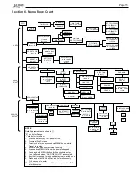

Page 6
Section 2. Installation of the User
Interface
2.1 Introduction
This document provides general instructions to install the
user interface for use with the Jandy ePump
TM
variable speed
pump. The user interface can be mounted to an electrical gang
box (single, double, or triple) or to a flat wall.
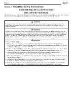
The instructions have been written with safety as the priority,
and must be followed exactly. Read through the instructions
completely before starting the procedure.
2.2
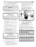
The User Interface Panel
The user interface panel provides both timed and manual
speed controls for the Jandy ePump
TM
Variable Speed Pump.
Four speed presets are directly available on the panel, while
four (4) additional presets may be accessed via the
MENU
key.
The up and down keys are used to adjust the pump speed.
Speed is saved as it is adjusted. No further action is required
to save the new speed setting after adjustment. The selected
speed can be saved and assigned to one of the speed buttons.
As shown in Figure 1, preset speed "
" is assigned to
the "eStar" feature. Hence, it is intended to be assigned
an energy-efficient filtration speed, as determined by the
installer.
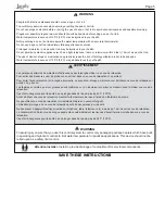
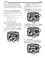
Figure 1.
Jandy ePump
TM
Variable Speed Pump
User Interface Panel
LCD Display
Preset Speed
Buttons
Menu Button
LED Lights
Up/Down
Arrow Keys
2
3
4
PRESS PRESET OR MENU
12:00AM PUMP IS OFF
ePUMP
MENU
eStar Button
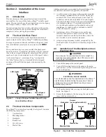
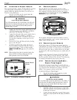
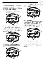
Figure 2.
User Interface Components
2.3
The User Interface Components
The ePump™ user interface assembly (See Figure 2) contains
the following components:
1. User
Interface
2. Mounting
Gasket
3. Backplate
4. Round
Seal
5.
Six (6) Screws
6. Plastic
Film
Additional materials are required for the installation of the
user interface and must be supplied by the installer:
1. A cable to connect the pump to the remotely mounted
user interface, minimum size of 22 AWG (Jandy part
number 4278). This cable will need to have four (4)
conductors and be able to handle 24V control signals.
This cable should be rated for the particular installation
(for example: outdoor, UV resistant, direct burial,
etc.) and should conform to all applicable codes and
regulations. (A suitable cable is included in the JEP
Series ePump water pumps.)
2. A minimum of two (2) fasteners to mount the user
interface back plate to a wall or electrical box. The
fasteners should be suitable for the surface where the
user interface is to be remotely mounted.
3. A
high-voltage
disconnect switch, as required by the
National Electric Code (NEC), within line of sight of the
pump.
2.4
Installation of the Backplate onto an
Electrical Box
CAUTION
Do not expose the user interface to direct sunlight. Too
much direct sunlight will darken the LCD screen, and it
will no longer be readable.
1. Turn off the pump at the control panel.
2. Turn off all electrical power to the pump at the main
junction box or at the circuit breaker providing electrical
power to the pump.
WARNING
ELECTRICAL SHOCK HAZARD
Turn off all switches and the main breaker in the ePump™
electrical circuit before starting the procedure. Failure to
comply may cause a shock hazard resulting in severe
personal injury or death.
3. Drill out the plastic film covering the backplate screw
holes. See Figure 2.
4. Secure the backplate to the box using the screws that
came with the electrical box.
Screws (6)
User Interface
Gasket
Backplate
Round Seal
Plastic Film
Screws
(not supplied with kit)
Breakout tabs
Содержание ePump
Страница 2: ......