background image

Page 7

2.2 

System Component Specifications and Dimensions

Table 1

Specifications (USA and Canada)

Power Supply

120 VAC; 60 Hz;  A

Contact Rating (Relays)

High voltage -   25 A; HP @ 20 VAC


1½ HP @120 VAC


1500 Watts Incandescent

Low Voltage -  Class Two, 1 A @ 2 VAC

Service Switch

All Circuits (located at Power Center in Service Mode)

Dimensions

Standard Power Center

5"

14½"

13¾"

Sub-Panel Power Center

20"

14½"

5"

Note  Breakers for Sub-Panel Power Center 

only.

PDA Handheld Remote

Front View

3½"

6¾"

Pool D

igital Assista

nt

1

2

select

back

PDA

7

/

8

"

Side View

J-Box Transceiver

1

/

16

"

Side View (at Angle)

4"

6"

1"

7"

Front View

Содержание AquaLink RS PDA

Страница 1: ...s These limits are designed to provide reasonable protection against harmful interference in a residential installation This equipment generates uses and can radiate radio frequency energy and if not...

Страница 2: ......

Страница 3: ...4 2 Restarting the System Clear Memory Menu 23 4 3 PDA System Defaults and General Modes 23 4 4 PDA Handheld Remote Menu Flow Chart 25 Section 5 Troubleshooting 26 5 1 PDA Quick Troubleshooting Guide...

Страница 4: ...egnant or possibly pregnant women should limit spa water temperatures to 100 F 38 C c Before entering a spa or hot tub the user should measure the water temperature with an accurate thermometer since...

Страница 5: ...ur health Do not permit any electric appliance such as a light telephone radio or television within 5 feet 1 5 m of a spa or hot tub The use of alcohol drugs or medication can greatly increase the ris...

Страница 6: ...ital Assistant PDA System Sub Assembly Power Centers Sold Separately Standard Power Center with mounting brackets Sub Panel Power Center with mounting brackets and circuit breaker mounting plate Two 2...

Страница 7: ...Watts Incandescent Low Voltage Class Two 1 A 24 VAC Service Switch All Circuits located at Power Center in Service Mode Dimensions Standard Power Center 5 14 13 Sub Panel Power Center 20 14 5 Note Br...

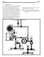
Страница 8: ...etween pool and spa consult the Jandy Valve Actuator Installation and Operation Manual to ensure that the JVAs are synchronized and rotate properly Please consult the Jandy Valve Plumbing Manual for f...

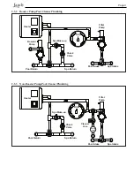
Страница 9: ...ilter Pump Pool Intake Spa Intake Spa Return Pool Return Check Valve Spa Make up Booster Pump 2 3 3 Non Booster Pump Pool Cleaner Plumbing Filter Filter Pump Pool Intake Spa Intake Spa Return Pool Ret...

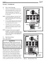
Страница 10: ...Power Center Filter Pump Relay Aux 3 Relay Transformer Earth Ground Black White Primary Low voltage raceway do not run high voltage in this compartment From Main Power Ground White White Black Black F...

Страница 11: ...the two 2 line terminals and connect equipment power to the two 2 load terminals on the same relay For each piece of 120 volt equipment connect power to a line terminal and connect equipment to a load...

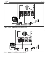
Страница 12: ...lling a 12 volt light a 120 volt 12 volt step down AC transformer listed certified for the application must be used For more information about 12 volt installations refer to the Jandy Digital Color Ch...

Страница 13: ...C Power Supply Junction Box Figure 5 120 Volt Jandy Pool and Spa Light Wiring Diagram Figure 6 12 Volt Jandy Pool and Spa Light Wiring Diagram GFCI Ground Ground Neutral Black White Green 12V Jandy Li...

Страница 14: ...es are kept from being pinched or damaged CAUTION DO NOT INSTALL BATTERY until ready to power up system 3 3 2 PDA J Box Cable Connection to Power Center PCB Make provision for the cable to be run betw...

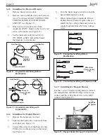
Страница 15: ...ure switches 4 Turn the heater thermostat s to maximum setting 5 Turn the heater switch to the ON position For dual thermostat heaters turn switch to Spa position Figure 9 Lite2 Heater Connection Powe...

Страница 16: ...ction configuration connect the orange black and black orange wires to one contact and the yellow black wire to the other contact see Figure 15 Limit Switch Factory Installed Wire Nut R Limit Switch R...

Страница 17: ...solar pump output on the PCB Set the time to 11 59 PM at 12 00 AM the AquaLink RS will auto relabel Solar as Heat Pump Otherwise the AquaLink RS will auto relabel Solar as Heat Pump within 24 hours 5...

Страница 18: ...n 10 Pin Terminal Bar 10 9 8 7 6 5 4 3 2 1 Note Do not coil the JVA wires inside Power Center To shorten the wire remove the JVA cover and disconnect the wire Shorten strip and reconnect 3 For alterna...

Страница 19: ...ceiver and the PDA Transceiver J box must be set to the same RF channel 1 At the Transceiver J box remove the cover to expose the PCB see Figure 20 Figure 20 PDA Transceiver J Box Internal View 2 On t...

Страница 20: ...e LEARN MODE 5 At the PCB in the Transceiver J box slide the Learn Switch to LEARN ON See Figure 22 SET RF CHANNEL RF CHANNEL 1 Use ARROW KEYS to set the RF CHANNEL Press SELECT to continue Pool Digit...

Страница 21: ...TUP Pool Digital Assistant 1 2 select back PDA SET TEMP POOL HEAT 80 F SPA HEAT 104 F Highlight an item and press SELECT Pool Digital Assistant 1 2 select back PDA SET TEMP POOL HEAT 80 F SPA HEAT 104...

Страница 22: ...ERAL LABELS LIGHT LABELS WTRFALL LABELS CUSTOM LABEL Pool Digital Assistant 1 2 select back PDA LABEL AUX1 GENERAL LABELS AUX1 AERATOR AIR BLOWER BACKWASH BOOSTER PUMP CHEM FEED CLEANER MORE Pool Digi...

Страница 23: ...MEMORY ERASING ALL SETTINGS please wait Figure 30 Clear Memory Menu 4 3 PDA System Defaults and General Modes Default Temperature Pool Spa Combination Default Pool Temp 80 F Default Spa Temp 102 F Def...

Страница 24: ...ws two 2 options for operating the pool equipment on the first day of operation Option 1 Once all programming of equipment is completed the AquaLink RS PDA will automatically review all programs and t...

Страница 25: ...CTION AIR TEMP DEGREES F C ENABLED DISABLED FAHRENHEIT CELCIUS SET TEMP PUMP LOCKOUT ENABLED DISABLED BOOST SET AQUAPURE SET OUTPUT AQUAPURE SET TIME HELP SERVICE DIAGNOSTICS START GO BACK EQUIPMENT O...

Страница 26: ...to the transceiver J box Also check the installation of the PPD on the power center PCB If the PPD is not seated correctly the system will not communicate PDA Handheld Remote backlight is on and the...

Страница 27: ...ches first turn off all equipment Do not program any auxiliaries until all DIP switches are set Turn off all equipment buttons then turn off power to the system finally turn off then on DIP switch 1 T...

Страница 28: ...minal bar To Sensors etc green terminal bar To Controller red terminal bar 4 3 2 1 6 5 4 3 2 1 Blue Red Black Red Black F Pump Aux 2 Aux 3 Aux 6 Aux 5 Aux 4 Relay Sockets 24 VDC output JVA Sockets 24...

Страница 29: ...ow speed IMPORTANT You must also install a Jandy Two Speed Relay DIP 3 ON AUX 3 Controls Spa Spillover Operates with Pool Spa Combination Turn this switch ON and when the AUX 3 button on the AquaLink...

Страница 30: ...Normal operation Factory adjustment when this switch is on temperature delays are eliminated and solar temperature is displayed Do not leave this switch in the ON position 6 Spare Aux activates with F...

Страница 31: ...No change 4 Heater cool down operates Heater cool down disabled 5 Normal operation Factory adjustment when this switch is on temperature delays are eliminated and solar temperature is displayed Do not...

Страница 32: ...1 Sprinkler 2 Sprinkler 3 Stereo Stream Swim Jet Timed Aux Valve s Wtr Feature Whirlpool 1 2 3 Back Basement Beach Bedroom Bug Cabana Color Wheel Deck Dock Drive East Entry Equipment Fan Fence Flood F...

Страница 33: ...Page 33 NOTES...

Страница 34: ...Page 34 NOTES...

Страница 35: ......

Страница 36: ...or accessories in conjunction with the product s 8 Chemical contamination of combustion air or improper use of sanitizing chemicals such as introducing sanitizing chemicals upstream of the heater and...

Отзывы: