background image

8

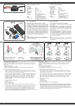
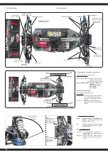
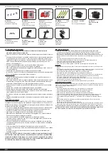
Collegamento della scheda di programmazione

Per collegare la scheda di programmazione al regolatore di velocità, scollegare il cavo del ventilato-

re (1) dal connettore tra i cavi del motore. Collegare il cavo alla scheda di programmazione, accer-

tandosi che il cavo sia collegato correttamente (vedi schema di collegamento, fi g. 2).  Assicurarsi di 

reinserire il cavo della ventola dopo aver completato la programmazione.

Connecting the programming card

To connect the programming card to the speed controller, disconnect the fan cable (1) from the 

connector between the motor cables. Connect the cable to the programming

card, making sure that the cable is connected correctly (see connection diagram, Fig. 2). Be sure to 

reinsert the fan cable after completing the programming.

Nota importante:

Oltre ai segnali lampeggianti del LED rosso, sono generati anche segnali acustici dal motore. Al 

termine di ogniprogrammazione, il regolatore deve essere prima spento. Dopo il riavvio, la nuova 

confi gurazione avrà effetto. 

Important note:

In addition to the red LED blinking, the motor will omit an acoustic signal. After every change to 

the values the ESC must be switched off to store the values. The new settings will not be effective 

until the ESC is re-started. 

IT 

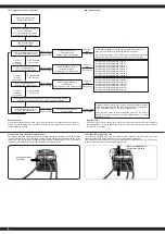
- Struttura del menu del regolatore

GB

 - Menu structure

Accendere il regolatore, mentre si

preme il tasto ‚SET‘.

Press and hold the ‘SET‘ button

down and switch the receiver on

Il LED rosso lampeggia

The red LED blinks

Accendere il trasmettitore

Switch transmitter ON

Il LED verde lampeggia una volta

The green LED blinks once

Il LED verde lampeggia 2 x

The green LED blinks twice

Il LED verde lampeggia 3 x

The green LED blinks 3 times

Il LED verde lampeggia X x

The green LED blinks X times

Premere il 

pulsante

per 3 secondi

Press the button

for 3 seconds

Premere il 

pulsante

per 3 secondi

Press the button

for 3 seconds

Premere il 

pulsante

per 3 secondi

Press the button

for 3 seconds

Lasciare il tasto

Release button

Lasciare il tasto

Release button

Lasciare il tasto

Release button

Lasciare il tasto

Release button

Premere il 

tasto

Press button

Premere il 

tasto

Press button

Premere il 

tasto

Press button

Premere il tasto

Press button

Programmazione Fase 1,

modalità di guida

Program option 1, Drive mode

Fase di programmazione 2,

modalità di frenata

Program option 2, Brake mode

Fase di programmazione 3,

sottotensione

Program option 3, Low voltage cut-off

Phase de programmation X

Program Option

Il LED rosso lampeggia una volta, cioè, signifi ca andare avanti con 

freno. Red LED blinks once indicating forwards and brake.

rote LED blinkt zweimal, d.h. Vorwärts- und Rückwärtsfahrt mit Bremse

The red LED blinks twice indicating forwards, reverse and brake.

rosso|red LED lampeggia|blinks 1x, ►0 %

rosso|red LED lampeggia|blinks 2x, ►5 %

rosso|red LED lampeggia|blinks 3x, ►10 %

rosso|red LED lampeggia|blinks 4x, ►15 %

rosso|red LED lampeggia|blinks 5x, ►20 %

rosso|red LED lampeggia|blinks 6x, ►25 %

rosso|red LED lampeggia|blinks 7x, ►30 %

rosso|red LED lampeggia|blinks 8x, ►40 %

rosso|red LED lampeggia|blinks 1x, ►aus

rosso|red LED lampeggia|blinks 2x, ►2,6 V

rosso|red LED lampeggia|blinks 3x, ►2,8 V

rosso|red LED lampeggia|blinks 4x, ►3 V

rosso|red LED lampeggia|blinks 5x, ►3,2 V

rosso|red LED lampeggia|blinks 6x, ►3,4 V

Si prega di premere il tasto ‚SET‘ per ogni modifi ca del valore corrente,

il LED rosso indica ciascuno dei valori, lampeggiare una volta signifi ca

che è impostato su valore 1, due volte sul valore 2 ecc.

Press the ‘SET‘ button to select the desired value. The red LED will 

indicate which value is selected. 1 X blink indicates value 1, 2 x blinks 

indicate value 2 etc.

Tutte le fasi seguenti di programmazione si svolgano nella stessa maniera.

All of the other menu options are accessed in the same manner.

Cavo della ventola

Fan cable

Schema di collegamento

Connect memory card

Содержание Ultra BL 8 2,4 GHz

Страница 1: ...h as weather location and interfering frequencies Therefore before each use perform a range test with a second person securely holding the model and also check how the model reacts if there is a signa...

Страница 2: ...g may result Please contact the manufacturer of your battery to find out whether your battery is suitable Only LiPo batteries with a capacity of at least 1600mAh must be used otherwise there is a risk...

Страница 3: ...t match then you will find a connection lead in your box Turn the radio on and make sure all the trim buttons on the transmitter are in neutral position Read the chapter for usage of the transmitter K...

Страница 4: ...di ca 1 2 mm Potrebbe essere necessario spostare il giunto omocinetico per adattare il gioco Qui deve svitare le vite senza testa con un cacciavite e regolare il giunto omocinetico Dopo di che avvita...

Страница 5: ...esse effettuare un nuovo allacciamento connessione eseguire le seguenti operazioni 1 Sostituire nella trasmettente le batterie scariche con altre cariche o nuove Lasciare spenta la trasmettente 2 Inse...

Страница 6: ...thrice Apprendimento della corsa gas freno Per prestazioni ottimali il regolatore deve essere calibrato In tal modo le tre posizioni avanti indietro e la posizione di folle devono essere specificata C...

Страница 7: ...anti per la prima volta nella zona inversa il motore frena Il veicolo si ferma ma non totalmente Ora se la leva viene premuto nuovamente nella zona inversa inverte il veicolo pero prima si ferma breve...

Страница 8: ...Premere il pulsante per 3 secondi Press the button for 3 seconds Premere il pulsante per 3 secondi Press the button for 3 seconds Lasciare il tasto Release button Lasciare il tasto Release button Lasc...

Страница 9: ...71 505073 505071 505085 505085 505155 505085 505058 059106 177463 059096 059097 505078 505075 505075 505060 505072 079996 079996 505072 Montaggio differenziale Differential assembly Montaggio di trasm...

Страница 10: ...ti si rischia di perdere gli alberi di trasmissi one La calotta esterna in plastica a 505080 serve solo per fissare il fuso a snodo sulla vite a sfera Consigliamo di non avvitare questo coperchio in m...

Страница 11: ...107 059100 059086 177443 059108 059070 059075 177143 059080 177143 059101 Montaggio ammortizzatore anteriore Front shock assembly Montaggio di snodo e protezione dagli impatti Front suspension and Bum...

Страница 12: ...3 059083 177443 059081 059074 Montaggio Ammortizzatore posteriore Rear shock assembly Installazione Ammortizzatore anteriore Front shock installation Montaggio servosaver Steering bell crank and servo...

Страница 13: ...58 177463 177463 059113 130158 505026 059085 505390 505388 505475 506119 Montaggio servo Servo assembly Montaggio del motore e pignone Motor mount assembly Montaggio frizione antisaltellamento Slipper...

Страница 14: ...97 059082 177443 059099 177143 059080 059108 059081 177463 505078 505075 505075 505028 079996 trasmissione posteriore di montaggio Rear gearbox assembly Montaggio posteriore a quadrilatero Rear Suspen...

Страница 15: ...01 059078 177143 177143 177143 505386 070806 505054 505054 505057 assemblaggio indietro Rear chassis area assembly Montaggio posteriore assale Rear hub assembly Montaggio superiore posteriore a quadri...

Страница 16: ...177463 177143 505386 177463 059081 059071 059083 177463 177463 Montaggio Ammortizzatore posteriore Rear shock assembly Montaggio barre scanalate e servo Steering rod set and servo set assembly L insta...

Страница 17: ...ff the pins on the body post set and insert it into the recess on the wing mount set Secure the pins with the set screws If the pins do not fit you can file them ricevitore e controllore di montaggio...

Страница 18: ...basso o meno clip Suspensione molla basso o meno clip Shock angle Inclinazione posteriore Inclinazione anteriore Toe front Inclinazione Caster Spring tension less or more clip Shock angle rear top Rea...

Страница 19: ...non precisa GB Negative positive camber front and rear You can adjust the front camber by turning one of the inner screws on the pivot front suspension Turn both screws equally inwards or outwards to...

Страница 20: ...per suspension set No 05 9104 Anello O perno per adatta tore ruota O ring and clip set No 05 9113 Direzzionale servo Servo pulling rod set No 50 5074 Cassa diff Differential case set No 05 9092 Carroz...

Страница 21: ...sta svasata Flat head cross screw No 05 9100 Font brace No 05 9085 M3 x 10 Vite del supporto del motore Button head cross screw No 50 5053 M3 x 6 Vita testa svasata Flat head cross screw No 50 5060 M3...

Страница 22: ...dicamente Il liquido contenuto nelle batterie dannoso per la pelle e per gli occhi In caso di contatto con gli occhi lavate abbondantemente con acqua e con sultate il medico In caso di contatto con la...

Страница 23: ...giocho tra pignone corona Regolatore di velocit si spegne durante la guida 1 Blocco della sottotensione tensione batteria bassa Caricare la batteria 2 Spegnimento per temperatura eccessiva Fare raffre...

Страница 24: ...batterie contengono delle sostanze che provocano irritazione possono causare allergie o sono altamente re attivi la raccolta differenziata e il riciclaggio sono importanti per l ambiente e la sua salu...

Отзывы: