

Wichtiger Hinweis:
Zusätzlich zu den Blinksignalen der roten LED werden auch entsprechende akustische Signale
vom Motor erzeugt. Nach jeder Programmierung muss der Regler zuerst ausgeschaltet werden.
Beim Wiedereinschalten wird die neue Konfiguration wirksam.
Important note:
In addition to the red LED blinking, the motor will omit an acoustic signal. After every change to
the values the ESC must be switched off to store the values. The new settings will not be effective
until the ESC is re-started.
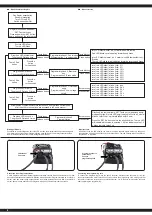
DE
- Menüstruktur des Reglers
GB
- Menu structure
Regler einschalten, und dabei
’SET’-Taste drücken
Press and hold the ‘SET‘ button
down and switch the receiver on
Die rote LED blinkt
The red LED blinks
Den Regler ausschalten
Sender einschalten
Turn OFF the ESC
Switch transmitter ON
Die grüne LED blinkt einmal
The green LED blinks once
Die grüne LED blinkt 2 x
The green LED blinks twice
Die grüne LED blinkt 3 x
The green LED blinks 3 times
Die grüne LED blinkt X x
The green LED blinks X times
Taste 3 Sek.
halten
Press the
button
for 3 seconds
Taste 3 Sek.
halten
Press the
button
for 3 seconds
Taste 3 Sek.
halten
Press the
button
for 3 seconds
Taste lösen
Release button
Taste lösen
Release button
Taste lösen
Release button
Taste lösen
Release button
Taste drücken
Press button
Taste drücken
Press button
Taste drücken
Press button
Taste drücken
Press button
Programmierphase 1, Fahrmodus
Program option 1, running mode
Programmierphase 2, Bremsmo-
dus
Program option 2, Brake mode
Programmierphase 3, Unterspan-
nung
Program option 3, Low voltage
cut-off
Programmierphase X
Program Option
rote LED blinkt einmal, d.h. Vorwärtsfahrt mit Bremse
Red LED blinks once indicating forwards and brake.
rote LED blinkt zweimal, d.h. Vorwärts- und Rückwärtsfahrt mit
Bremse
The red LED blinks twice indicating forwards, reverse and brake.
rote | red LED blinkt | blinks 1 x ► 0 %
rote | red LED blinkt | blinks 2 x ► 5 %
rote | red LED blinkt | blinks 3 x ► 10 %
rote | red LED blinkt | blinks 4 x ► 15 %
rote | red LED blinkt | blinks 5 x ► 20 %
rote | red LED blinkt | blinks 6 x ► 25 %
rote | red LED blinkt | blinks 7 x ► 30 %
rote | red LED blinkt | blinks 8 x ► 40 %
rote | red LED blinkt | blinks 1 x ► aus
rote | red LED blinkt | blinks 2 x ► 2,6 V
rote | red LED blinkt | blinks 3 x ► 2,8 V
rote | red LED blinkt | blinks 4 x ► 3 V
rote | red LED blinkt | blinks 5 x ► 3,2 V
rote | red LED blinkt | blinks 6 x ► 3,4 V
Drücken Sie bitte jeweils die ’SET’-Taste zur Veränderung des je-
weiligen Wertes, die rote LED zeigt jeweils die Werte an, einmal
blinken heißt Wert 1, zweimal blinken heißt 2, usw.
Press the ‘SET‘ button to select the desired value. The red LED
will indicate which value is selected. 1 X blink indicates value 1, 2
x blinks indicate value 2 etc.
Alle weiteren Programmierschritte laufen nach dem gleichen Verfahren ab
All of the other menu options are accessed in the same manner.
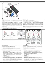
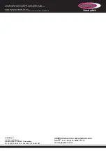
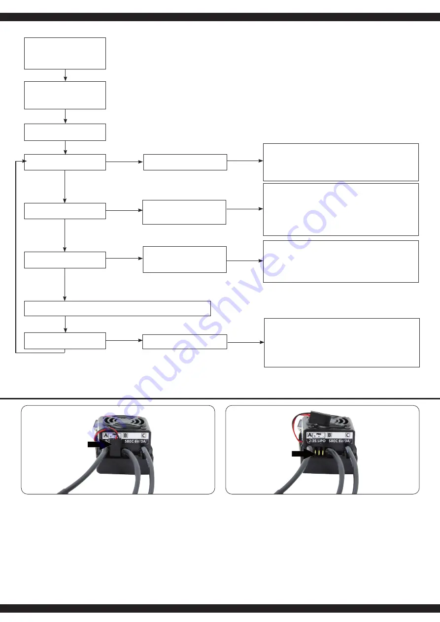
Anschluss einer Programmierkarte
Um die Programmierkarte am Speedregler anzuschließen, trennen Sie das Lüfterkabel (1) vom dem
Anschluss zwischen den Motorkabeln. Stecken Sie das Kabel der Programmierkarte an, achten Sie
darauf, dass das Kabel richtig angeschlossen wird (siehe Anschluss-Schema Bild 2). Achten Sie
darauf, dass Sie nach Abschluss der Programmierung das Lüfterkabel wieder einstecken.
Connecting the programming card
To connect the programming card to the speed controller, disconnect the fan cable (1) from the
connector between the motor cables. Connect the cable to the programming card, making sure that
the cable is connected correctly (see connection diagram, Fig. 2). Be sure to reinsert the fan cable
after completing the programming.
Lüfterkabel
Fan cable
Programmierkarte
anschließen
Connect
programming card
4
Содержание Speed controller CRB60WP
Страница 7: ...7...


