JR(H/V)(B)70
Installation
3
www.jakkagroup.com
INSTALLATION OF THE UNIT
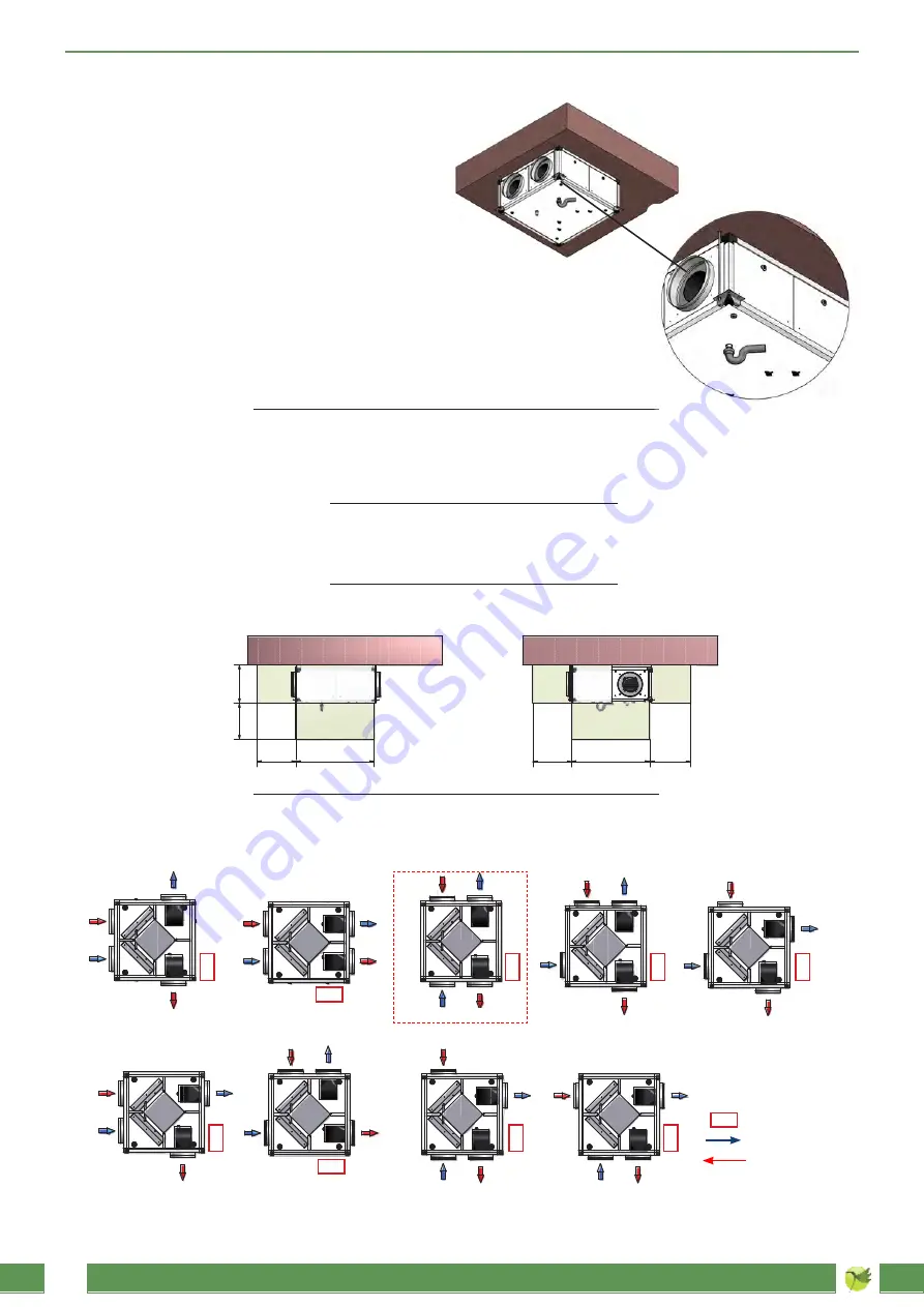
CEILING INSTALLATION
(horizontal configuration
The unit is equipped with lifting rods in the four unit angles, where
hooking is possible through threaded bars or chains in order to
facilitate ceiling fastening and levelling (see the draw).
After fastening the unit in the right position, carry out the connec-
tion to the ducting, the connection to the supply mains through the
terminal board boxes and the condensate discharge pipe fastening
on the air exhaust side.
JRH(B)70/900
JRH(B)70/2000
JRH(B)70/3000
JRH(B)70/4500
JRH(B)70/5600
MINIMUN SPACES REQUIRED FOR THE ORDINARY MAINTENANCE (in mm.)
Mod. A
B
C
D
360
535
630
855
855
400
400
500
500
500
400
600
700
900
900
820
1040
1270
1300
1300
A
C
B
D
D
B
B
HORIZONTAL CONFIGURATION (top view)
NO FAN POSITIONING IS PERMITTED ACCORDING TO SCHEMES OTHERS THAN THE ABOVE SCHEME
fresh air
exhaust air
AH
BH
CH
Standard configuration
DH
EH
electric board
FH
G
H
H
H
I
H


