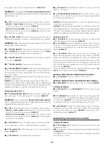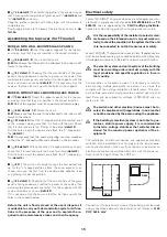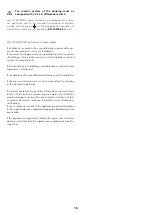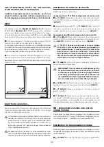
12
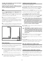
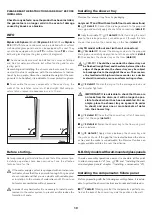
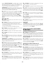
TB MODEL WITH SEAT
I
(
i
9 detail 1
) Accurately apply silicone around the holes in
the shower tray.
I
(
i
9 details 3-4
) Place the fixture panel on the shower tray
and insert it into the compensator, making sure that:
- the bushes in the bottom part of the fixture panel fit into the
holes in the shower tray.
- the pipes coming from the floor pass inside the bushes.
I
(
i
10 detail 1
)
Temporarily
fasten the fixture panel with the
“safety” screws as shown.
I
(
i
10 detail 2
)
Partially
tighten the screws shown.
I
(
i
11A detail 1
) Fasten the fixture panel to the shower tray
as shown.
I
(
i
11A detail 2
) Connect the mixer unit flexible hoses to the
water supply pipes, checking for watertightness (
detail 3
).
NB:
(
i
11.A detail 4
)
There is a terminal inside the fixture panel,
marked with a symbol as shown, for the equipotential connection.
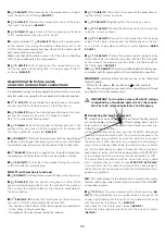
I
(
i
11.3
) Mark the given measurement on the shower tray
(
detail 1
). Using the dotted line as a guide, place an upright on
the shower tray, checking that the centre of the crossbar match-
es up with the mark on the shower tray (
detail 3
).
Also check that the fixture panel is level (
detail 4
).
Fasten the fixture panel permanently with the screws as shown
(
detail 5
).
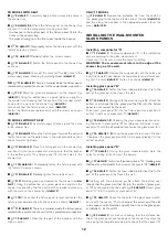
TB MODEL WITHOUT SEAT
I
(
i
11B detail 1
) Accurately apply silicone around the holes
in the shower tray.
I
(
i
11B detail 2
) Move the fixture panel towards the wall and
fasten the mixer unit flexible hoses to the wall connections, then
check for water tightness.
I
(
i
11B detail 3
) Place the fixture panel on the shower tray
and insert it into the compensator, making sure that the bushes
in the bottom part of the fixture panel fit into the holes in the
shower tray.
I
(
i
11B detail 4
)
Temporarily
fasten the fixture panel with
the “safety” screws as shown.
I
(
i
11B detail 5
)
Partially
tighten the screws shown.
I
(
i
11C
) Mark the given measurement on the shower tray (
de-
tail 1
). Using the dotted line as a guide, place an upright on the
shower tray, checking that the centre of the crossbar matches up
with the mark on the shower tray (
detail 3
).
I
(
i
11D
) Check that the fixture panel is level and fasten the
fixture panel permanently with the screws as shown (
detail 2
).
I
(
i
11.D detail 3
)
There is a terminal inside the fixture panel,
marked with a symbol as shown, for the equipotential connection.
I
(
i
12 detail 1
) Close the top part of the crossbar with the
click-on cover.
ONLY TT MODEL
(
i
12 detail 2
) Remove the protective film from the seals (in
the packaging for the top) and fasten one at the end (
detail 3a
)
and two along the crossbar, in the appropriate places (over the
cover,
detail 3b
).
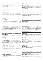
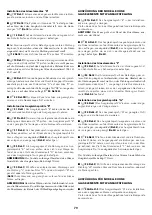
INSTALLING THE WALL-MOUNTED
GLASS PANELS
Installing compensator “A”
I
(
i
13 detail 1
) Position compensator “A” in the installation
corner according to the given measurement.
Check that it is level and mark the holes for drilling.
WARNING!
The measurement refers to the edge of the
shower tray, not the wall.
I
(
i
13 detail 2
) Remove the compensator, drill the holes and
insert the dowels. Then replace the compensator and, after check-
ing that it is level (
detail 3
), fasten it as shown (
detail 4
).
Installing glass panel "B"
I
(
i
14 detail 1
) Fasten the foam rubber protective strip to the
part of the glass panel that faces the wall.
I
(
i
14 detail 2
) Starting with the aluminium profile, attach the
bottom seal
(check that the glass part that fits into the fixture
panel is not covered by the seal)
.
Then insert glass panel “B” into the fixture panel and position it
so that it rests on compensator “A” (
detail 3
).
I
(
i
15 details 1-2
) Checking the given measurements and us-
ing the holes in glass profile “B” for reference, drill holes in com-
pensator “A” with the bit provided, then fasten the glass panel to it.
I
(
i
16 details 1-2
) Using the appropriate tool, insert the seal
“L” between the glass panel and the fixture panel, placing it in the
correct position.
Installing glass panel "D"
I
(
i
17 detail 1
) Using the given measurements, mark the
holes for drilling, drill and insert the dowels.
I
(
i
17 detail 2
) Fasten the threaded cylinders “S1”
(making sure
that the slot is horizontal)
; then screw on the covers “S2” (
detail 3
).
I
(
i
18 detail 1
) Fasten the foam rubber protective strip to the
part of the glass panel that faces the wall.
I
Starting with the aluminium profile, attach the bottom seal
(check that the glass part that fits into the profile of glass pan-
el “B” is not covered by the seal)
. (
i
18 detail 2
) Insert glass
panel "D" into the profile of glass panel “B”.
I
(
i
19 detail 1
) Check tha the hole in the glass panel match-
es up with the spacer “S”;
if not, adjust the screw and the slot
in the spacer, until it matches up with the hole in the glass pan-
el (details A, B, C and D).
I
(
i
20 detail 1
) As well as checking that the distance be-
tween the glass panel and the edge of the shower tray stays the
same,using the template provided, also check that the spacer “S”


