background image

GB-5

JACOBSEN  AR3

NARROW WIDTH OF CUT FIELD KIT

FITTING INSTRUCTIONS

Release blockages with care. Keep all parts
of the body away from the cutting edge.
Beware of energy in the drive which can
cause rotation when the blockage is released.

Keep other people away from the cutting units
as rotation of one cylinder can cause the
others to rotate.

2.9

ADJUSTMENTS, LUBRICATION AND
MAINTENANCE

Stop the engine and make sure all moving
parts are stationary.

Apply brakes and disengage all drives.

Read all the appropriate servicing instructions.

Use only the replacement parts supplied by
the original manufacturer.

When adjusting the cutting cylinders take
care not to get hands and feet trapped when
rotating cylinders.

Make sure that other people are not touching
any cutting units, as rotation of one cylinder
can cause the others to rotate.

To reduce the fire hazard, keep the engine,
silencer and battery compartments free of
grass, leaves or excessive grease.

Replace worn or damaged parts for safety.

When working underneath lifted parts or
machines, make sure adequate support Is
provided.

Do not dismantle the machine without
releasing or restraining forces which can
cause parts to move suddenly.

DANGER - Indicates an imminently hazardous
situation which, if not avoided, WILL result in death
or serious injury.

WARNING - Indicates a potentially hazardous
situation which, if not avoided, COULD result in
death or serious injury.

CAUTION - Indicates a potentially hazardous
situation which, if not avoided, MAY result in minor
or moderate injury and property damage.  It may
also be used to alert against unsafe practices.

2

SAFETY INSTRUCTIONS

Содержание AR3

Страница 1: ...in its proper use warned of its dangers and should read the entire manual before attempting to set up operate adjust or service the machine FITTING INSTRUCTIONS RJ 100 08 2005 24772G GB rev 1 AR3 Narr...

Страница 2: ...2005 Ransomes Jacobsen Limited All Rights Reserved...

Страница 3: ...ARATION 6 3 2 IMPORTANTNOTE 6 4 FRONT LH LIFT ARM 4 1 REMOVECUTTINGUNITFROMLIFTARM 7 4 2 DISCONNECT LIFT RAM FROM LIFT ARM 7 4 3 REMOVELIFTARMFROMFRONTAXLE 7 4 4 ASSEMBLENEWLIFTARMTOFRONTAXLE 8 4 5 RE...

Страница 4: ...unpredictable Keep travelling speeds low enough for an emergency stop to be effective and safe at all times in any conditions Remove or avoid obstructions in the area to be cut thus reducing the possi...

Страница 5: ...ke sure that other people are not touching any cutting units as rotation of one cylinder can cause the others to rotate To reduce the fire hazard keep the engine silencer and battery compartments free...

Страница 6: ...und engage parking brake stop the engine and remove key from ignition switch a Wait for all movement to stop before making any adjustments or modifications b Take this opportunity to thoroughly inspec...

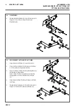
Страница 7: ...Shaft 5 Retain items B C D and E for future use 4 FRONT LH LIFT ARM 4 2 DISCONNECT LIFT RAM FROM LIFT ARM 1 Remove Ram Pin B from Lift Arm A 2 Retain Ram Pin B and all hardware D E and Nyloc Nut for f...

Страница 8: ...t Arm Pivot Pin E through Front Axle Z Nylon Washers F and Lift Arm A Pivot Housing Note Lift Arm Pivot Pin E is assembled so that the flange plate is on the outside of the machine 7 Align hole in Lif...

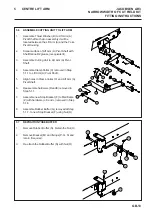
Страница 9: ...Lift Arm A Pivot Shaft so that on assembly it will be located between the Lift Arm A and the Yoke PivotHousing 2 Smear surface of Lift Arm A Pivot Shaft with ShellDarinaR2grease orequivalent 3 Assembl...

Страница 10: ...Cutting Unit from Lift Arm A 3 Remove Thrust Washer B from Lift Arm A PivotShaft 4 Retain items B C D and E for future use 5 Remove Stop Bracket F from Mainframe 6 Retain items J K and L for future us...

Страница 11: ...ME 1 Smear bore of new Lift Arm A bushes with ShellDarinaR2grease orequivalent 2 Clean surface of Lift Arm Pivot Pin E removed in Step 5 3 2 to remove old grease residue 3 Smear Lift Arm Pivot Pin E w...

Страница 12: ...T ARM 1 Align holes in Lift Ram Y and Lift Arm A 2 Clean surface of Ram Pin B removed in Step 5 2 1 to remove old grease residue 3 Smear surface of Ram Pin B with Shell Darina R2grease orequivalent No...

Страница 13: ...ivot Shaft 4 Assemble Clamp Collar C removed in Step 5 1 1 to Lift Arm A Pivot Shaft 5 Align holes in Clamp Collar C and Lift Arm A PivotShaft 6 Reassemblehardware DandE removedin Step 5 1 1 7 Assembl...

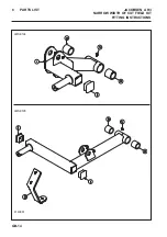
Страница 14: ...GB 14 JACOBSEN AR3 NARROW WIDTH OF CUT FIELD KIT FITTING INSTRUCTIONS 6 PARTS LIST LMSE194 LMSE195 4140881...

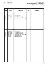
Страница 15: ...nd Cap RHS 50x50x5 1 2 002993160 Lubricator M6 x 90 Deg 1 3 4130255 Bush Devol 1 1 4 x 1 5 8 x 1 1 2 2 4 4140813 Wldmt Lift Arm LH 1 LMSE195 LiftArm Centre 1 1 002952633 End Cap RHS 50x50x5 2 2 002993...

Страница 16: ...GB 16 JACOBSEN AR3 NARROW WIDTH OF CUT FIELD KIT FITTING INSTRUCTIONS 6 PARTS LIST 2 1...

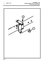
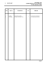
Страница 17: ...ROW WIDTH OF CUT FIELD KIT FITTING INSTRUCTIONS ITEM PART No DESCRIPTION QTY REMARKS 1 4142585 Bracket BumperStop 1 re used part as instructed 2 450120398 Nut Hex 3 8 16 Nyloc Thin 1 re used part as i...

Страница 18: ...GB 18 JACOBSEN AR3 NARROW WIDTH OF CUT FIELD KIT FITTING INSTRUCTIONS 7 NOTES...

Страница 19: ......

Страница 20: ...etwork and factory trained technicians backed by Ransomes Jacobsen Parts Xpress provide reliable high quality product support RansomesJacobsenLimited West Road Ransomes Europark Ipswich England IP3 9T...

Отзывы: