Jackson CONSERVER XL Скачать руководство пользователя страница 4

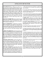
VISUAL INSPECTION:

Before installing the unit, check the con-

tainer and machine for damage. A damaged container is an indi-
cator that there may be some damage to the machine. If there is
damage to both the container and machine, do not throw away the
container. The dishmachine has been inspected and packed at
the factory and is expected to arrive to you in new, undamaged
condition. However, rough handling by carriers or others may
result in there being damage to the unit while in transit. If such a
situation occurs, do not return the unit to Jackson; instead, contact
the carrier and ask them to send a representative to the site to
inspect the damage to the unit and to complete an inspection
report. You must contact the carrier within 48 hours of receiving
the machine. Also, contact the dealer through which you pur-
chased the unit.

UNPACKING THE DISHMACHINE:

Once the machine has been

removed from the container, ensure that there are no missing
parts from the machine. This may not be obvious at first. If it is dis-
covered that an item is missing, contact Jackson immediately to
have the missing item shipped to you. 

LEVEL THE DISHMACHINE:

The dishmachine is designed to

operate while being level. This is important to prevent any dam-
age to the machine during operation and to ensure the best
results when washing ware. The unit comes with adjustable bullet
feet, which can be turned using a pair of channel locks or by hand
if the unit can be raised safely. Ensure that the unit is level from
side to side and from front to back before making any connec-
tions.

PLUMBING THE DISHMACHINE:

All plumbing connections must

comply with all applicable local, state, and national plumbing
codes. The plumber is responsible for ensuring that the incoming
water line is thoroughly flushed prior to connecting it to any com-
ponent of the dishmachine. It is necessary to remove all foreign
debris from the water line that may potentially get trapped in the
valves or cause an obstruction. Any valves that are fouled as a
result of foreign matter left in the water line, and  any expenses
resulting from this fouling, are not the responsibility of the manu-
facturer.

CONNECTING THE DRAIN LINE:

The drain for the Conserver XL

is a gravity discharge drain. All piping from the 2” MNPT connec-
tion on the waste accumulator must be pitched (1/4” per foot) to
the floor or sink drain. All piping from the machine to the drain
must be a minimum 2” I.P.S. and shall not be reduced. There must
also be an air gap between the machine drain line and the floor
sink or drain. If a grease trap is required by code, it should have a
flow capacity of 5 gallons per minute.

WATER SUPPLY CONNECTION: 

Ensure that you have read the

section entitled “PLUMBING THE DISHMACHINE” above before
proceeding. Install the water supply line (3/4” pipe size minimum)
to the dishmachine line strainer using copper pipe. It is recom-
mended that a water shut-off valve be installed in the water line
between the main supply and the machine to allow access for ser-
vice. The water supply line is to be capable of 20 PSI “flow” pres-
sure at the recommended temperature indicated on the data plate. 

In areas where the water pressure fluctuates or is greater than the
recommended pressure, it is suggested that a water pressure reg-
ulator be installed. 

Do not confuse static pressure with flow pressure. Static pressure
is the line pressure in a “no flow” condition (all valves and services
are closed). Flow pressure is the pressure in the fill line when the
fill valve is opened during the cycle.

It is also recommended that a shock absorber (not supplied with
the Conserver XL model) be installed in the incoming water line.
This prevents line hammer (hydraulic shock), induced by the sole-
noid valve as it operates, from causing damage to the equipment.

PLUMBING CHECK:

Slowly turn on the water supply to the

machine after the incoming fill line and the drain line have been
installed. Check for any leaks and repair as required. All leaks
must be repaired prior to placing the machine in operation.

ELECTRICAL POWER CONNECTION:

Electrical and grounding

connections must comply with the applicable portions of the
National Electrical Code ANSI/NFPA 70 (latest edition) and/or
other electrical codes.

Disconnect electrical power supply and place a tag at the discon-
nect switch to indicate that you are working on the circuit.

The dishmachine data plate is located on the right side and to the
front of the machine. Refer to the data plate for machine operat-
ing requirements, machine voltage, total amperage load and seri-
al number.

To install the incoming power lines, open the control box. This will
require taking a phillips head screwdriver and removing the one(1)
screw on the front cover of the control box. Install 3/4” conduit into
the pre-punched holes in the back of the control box. Route power
wires and connect to power block and grounding lug. Install the
service wires (L1 & N) to the appropriate terminals as they are
marked on the terminal block. Install the grounding wire into the
lug provided.

It is recommended that “DE-OX” or another similar anti-oxidation
agent be used on all power connections.

VOLTAGE CHECK:

Ensure that the power switch is in the OFF

position and apply power to the dishmachine. Check the incoming
power at the terminal block and ensure it corresponds to the volt-
age listed on the data plate. If not, contact a qualified service
agency to examine the problem. Do not run the dishmachine if the
voltage is too high or too low. Shut off the service breaker and
mark it as being for the dishmachine. Advise all proper personnel
of any problems and of the location of the service breaker.
Replace the control box cover and tighten down the screws. 

INSTALLATION INSTRUCTIONS

2

Содержание CONSERVER XL

Страница 1: ...SERVICE M MANUAL October 24 2001 P N 7610 002 10 23 Revision B Visit Jackson on the Internet at www jacksonmsc com CONSERVER XL ...

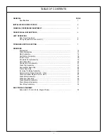
Страница 2: ...rol Box Assembly 16 8 Cam Timer 18 Peristaltic Pump Assembly 19 Hood Assembly 20 Cantilever Arm Assembly 21 Wash Tub Assembly 22 Accumulator Assembly 23 Frame Assembly 24 Incoming Plumbing Assembly 25 Solenoid Valve Repair Kits 3 4 110V 26 Vacuum Breaker Repair Kit 3 4 NPT 27 Wash Motor Assembly 28 Wash Arm Assembly 29 Wash Manifold Assembly 30 Drain Solenoid Assembly 31 Door Wrap Assembly 32 ELEC...

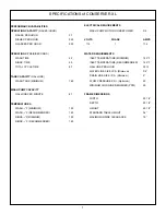
Страница 3: ...MENDED 140 RINSE F MINIMUM 120 RINSE F RECOMMENDED 140 ELECTRICAL REQUIREMENTS WASH PUMP MOTOR HORSEPOWER 3 4 VOLTS PHASE AMPS 115 1 11 4 WATER REQUIREMENTS INLET TEMPERATURE MINIMUM 120 F INLET TEMPERATURE RECOMMENDED 140 F GALLONS PER HOUR 55 13 WATER LINE SIZE I P S Minimum 3 4 DRAIN LINE SIZE I P S Minimum 2 FLOW PRESSURE P S I Optimum 20 MINIMUM CHLORINE REQUIRED PPM 50 FRAME DIMENSIONS WIDTH...

Страница 4: ...all the water supply line 3 4 pipe size minimum to the dishmachine line strainer using copper pipe It is recom mended that a water shut off valve be installed in the water line between the main supply and the machine to allow access for ser vice The water supply line is to be capable of 20 PSI flow pres sure at the recommended temperature indicated on the data plate In areas where the water pressu...

Страница 5: ...eri staltic pumps One will prime the sanitizer pump only and the second will prime either the detergent or rinse aid pump depending upon which way it is depressed 3 To prime the pumps hold the switch in the momentary position until chemical can be observed entering the sump 4 Detergent is dispensed as required during the wash cycle by the cam timer The amount of detergent may need to be increased ...

Страница 6: ...e Scraps should be removed from ware prior to being loaded into a rack Pre rinsing and pre soak ing are good ideas especially for silverware and casserole dish es Place cups and glasses upside down in racks so that they do not hold water during the cycle The dishmachine is meant not only to clean but to sanitize as well to destroy all of the bacteria that could be harmful to human beings In order ...

Страница 7: ...ent due to varying water pressure The fill solenoid must remain open a sufficient length of time to fill the machine to the correct level SETTINGS The right side of cam 4 must be set to allow the switch arm to drop 2 seconds before the drain solenoid is de ener gized which flushes the detergent residue from the unit It will hold the fill solenoid open until the cam switch arm is raised At that tim...

Страница 8: ... energized closed Controlled by C3 cam 54 SECONDS INTO CYCLE Sanitizer pump is energized injecting sanitizer into wash tank Controlled by C5 cam Rinse aid pump is energized injecting rinse aid into wash tank Controlled by C7 cam 58 SECONDS INTO CYCLE Sanitizer pump is de energized The length of time that the sanitizer pump is activated will be determined in the field Timing will depend on the chem...

Страница 9: ...ITE wires on the cycle reset switch If it is 120V then the switch is open and should be replaced Faulty cam timer motor If cam timer is not rotating check the voltage to the motor If voltage is present when the door is closed replace the motor Faulty control relay Check the voltage across contacts 9 and 6 If 120V when the door is closed replace the relay Faulty NORMAL DELIME switch In the NORMAL p...

Страница 10: ...age but no continuity replace coil continuity is measured across coil connectors with wires removed Faulty fill microswitch Will not fill during cycle only During fill measure between the ORANGE and WHITE GREEN wires If 120V adjust or replace switch Faulty OFF ON FILL switch Depress switch measure between BLACK and WHITE GREEN wire If 120V replace switch Solenoid valve dirty or faulty Clean valve ...

Страница 11: ...lays High or low voltage problem Check voltage at motor and at power terminal block Compare to electrical specifications The NORMAL DELIME switch is in the Delime position Place the switch in the Normal position Wash relay contacts are welded closed Turn machine off If wash relay doesn t release replace contactor Cam timer stalled in wash or rinse cycle If cam timer is not rotating check the volta...

Страница 12: ...t fill cam on timer and or the drain cam Drain linkage binding Repair drain parts Faulty drain microswitch on timer With power off and the drain cam on the timer in the home position remove the WHITE YELLOW wire from the microswitch Faulty drain microswitch on timer Measure the continuity between the ORANGE wire on the microswitch and the tab that the WHITE YELLOW wire is attached onto If there is...

Страница 13: ...he microswitch Misadjusted cam Adjust rinse aid cam on cam timer Faulty rinse aid microswitch on cam timer When the rinse aid cam is in the home position measure the voltage between the ORANGE and ORANGE YELLOW wires If 120V replace the microswitch Loose or broken wire Tighten connections to microswitch Faulty sanitizer microswitch on cam timer When sanitizer cam is in home position measure voltag...

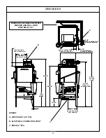
Страница 14: ... 4 5 TOP OF MACHINE TO C OF ELEC CON 3 3 4 15 1 4 EDGE OF WATER INLET TO SIDE OF MACHINE 4 BACK OF CONTROL BOX TO BACK OF MACHINE 2 3 8 C OF WATER INLET TO BACK OF MACHINE SIDE OF MACHINE TO C OF ELEC CON C STANDARD CLEARANCE BETWEEN MACHINE AND WALL WITH DISHTABLE IS 4 B A LEGEND A WATER INLET 3 4 IPS B ELECTRICAL CONNECTION POINT C DRAIN 2 IPS ...

Страница 15: ...ORNER INSTALLATION TABLE DIMENSIONS CONNECTION TO DISHMACHINE TABLE DIMENSIONS STRAIGHT THROUGH INSTALLATION 20 1 2 OPENING 25 1 4 2 1 4 4 MIN 2 1 2 4 MIN 20 1 2 OPENING 25 1 4 20 1 2 3 4 1 1 2 ROLL 4 MIN 2 1 2 25 1 4 20 1 2 OPENING 25 1 4 ...

Страница 16: ...MAIN ASSEMBLY 14 1 2 3 4 NOT SHOWN 5 6 7 8 11 12 13 NOT SHOWN 9 10 NOT SHOWN 14 ...

Страница 17: ...930 111 41 70 6 2 Screw 8 32 x 3 4 for Hood Magnet 5305 011 72 66 7 2 Lockwasher Internal Tooth 8 5311 272 03 00 8 1 Cover Weldment Hood Mounted Reed Sw 5700 002 04 68 9 1 Door Front 5700 002 01 28 10 1 Door Left 5700 002 03 01 11 1 Stand Pipe Assembly 5700 002 04 46 1 Stand Pipe 5700 002 04 47 1 Stopper Stand Pipe 5700 121 35 54 12 1 Rack Guide Assembly 5700 031 36 76 13 4 Locknut 1 4 20 with Nyl...

Страница 18: ...CONTROL BOX ASSEMBLY 16 ...

Страница 19: ...75 200 40 00 21 1 Control Relay 5945 111 35 19 22 1 Conduit Fitting 1 2 45 DEG Plastic 5975 011 45 23 23 1 Conduit Fitting 1 2 Straight Plastic 5975 011 45 13 24 1 Motor Peri Pump 14 RPM 4320 111 35 13 25 2 Motor Peri Pump 36 RPM 4320 111 35 14 26 1 Grommet 5325 011 46 73 27 1 Fitting Brass 4730 206 23 00 28 2 Nut Lock 5700 000 66 01 29 4 Screw 4 40 x 1 4 Long 5305 002 32 38 Other parts not shown ...

Страница 20: ...8 CAM TIMER 18 CYCLE RESET WASH DRAIN FILL SANITIZER DETERGENT RINSE AID SPARE CAM ITEM QTY DESCRIPTION MFG No 1 1 Timer Motor 5945 306 14 00 2 8 Microswitch 5930 011 65 81 02 01 ...

Страница 21: ...ller 4320 111 36 70 4 1 Peri Pump Squeeze Tube 5700 111 35 29 5 4 Screw 6 32 x 3 4 Phillips Pan Head 5305 011 37 05 6 1 Screw 8 32 x 1 2 Phillips Flat Head 5305 011 37 06 7 1 Housing Rear Assy 4320 111 37 09 8 1 Peri Pump Motor 14 RPM Rinse Additive 4320 111 35 13 9 2 Peri Pump Motor 36 RPM Detergent Sanitizer 4320 111 35 14 ITEM NOT SHOWN 1 2 3 4 5 6 7 8 ...

Страница 22: ... 5700 002 05 74 5 1 Left Door Guide 5700 002 05 75 6 4 Door Guide 5700 002 05 73 7 26 Locknut 1 4 20 with Nylon Insert S S 5310 374 01 00 8 26 Washer 1 4 20 5311 174 01 00 9 22 Bolt 1 4 20 x 1 2 Long 5305 274 02 00 10 2 Bolt 1 4 20 x 3 4 Long 5305 274 04 00 11 2 Support Cantilever Arm Assembly 5700 002 04 45 2 Suppor Bracket 5700 031 88 00 6 Wear Buttons 5700 011 88 01 11 ...

Страница 23: ... 000 69 45 8 2 Support Cantilver Arm Assembly 5700 002 04 45 9 8 Washer 1 4 20 S S 5311 174 01 00 10 4 Locknut 1 4 20 with Nylon Insert S S 5310 374 01 00 11 2 Cantilever Arm Connector 5700 011 90 99 12 2 Yoke Assembly 5700 000 75 77 13 2 Plug Cantilver Arm 5340 011 35 00 14 2 Locknut 3 8 16 5310 256 04 00 15 2 Spring 5340 109 03 00 16 N A 17 N A 18 4 Locknut 1 4 20 with Nylon Insert Low Prof 5310...

Страница 24: ...1 Fitting Chemical Drip 5700 002 05 62 3 1 Spillway Weldment 5700 002 04 41 4 2 Drain Seat Gasket 5700 002 04 42 5 1 Sump Strainer 5700 002 06 25 6 1 Drain Seat Insert 5700 021 34 38 7 1 Bulkhead to 1 2 Hosebarb Fitting 4730 011 45 21 8 4 Locknut 10 24 with Nylon Insert 5310 373 01 00 ...

Страница 25: ...FG No 1 1 Accumulator Weldment Conserver XL 5700 002 04 63 2 1 Accumulator Strainer 5700 002 00 38 3 6 Bolt 1 4 20 x 1 2 Long 5305 274 02 00 4 6 Washer S S 1 4 20 5311 174 01 00 5 6 Locknut 1 4 20 with Nylon Insert S S 5310 374 01 00 ITEM NOT SHOWN ...

Страница 26: ...er XL 5700 002 03 72 4 2 Bracket Spring Mounting 5700 002 04 37 5 1 Tub Support 5700 001 99 83 6 4 Bullet Feet 5340 108 02 06 7 9 Bolt 1 4 20 x 1 2 Long 5305 274 02 00 8 9 Washer Flat 1 4 ID 5311 174 01 00 9 11 Locknut 1 4 20 with Nylon Insert S S 5310 374 01 00 10 1 Leg Rear Left Frame Assembly 5700 002 24 69 11 1 Leg Rear Right Frame Assembly 5700 002 23 96 ...

Страница 27: ...T 4730 406 42 01 3 1 Vacuum Breaker Brass 3 4 4820 300 08 00 4 1 Solenoid Valve 3 4 NPT 100 Volt 4810 100 53 00 5 1 Adapter 3 4 MNPT 4730 401 11 01 6 1 Nipple Brass Close 3 4 NPT 4730 207 34 00 7 1 Strainer Brass Watts 3 4 NPT 4730 717 02 06 8 1 Adapter 3 4 4730 401 10 01 9 2 Locknut Brass 3 4 Bulkhead 4730 208 04 00 ITEM NOT SHOWN ...

Страница 28: ...ow Item 3 3 4 Diaphragm Retainer 5 Screen Retainer Mesh Screen Valve Body ITEM QTY DESCRIPTION MFG No 1 1 Coil Housing 115V 4810 200 01 18 2 1 Spring 4810 200 04 18 3 1 Plunger 4810 200 04 18 4 1 O Ring 4810 100 10 18 5 1 Diaphragm 4810 100 10 18 Order the entire solenoid valve using manufacturer part number 4810 100 53 00 ...

Страница 29: ...VACUUM BREAKER REPAIR KIT 3 4 NPT 27 CAP SCREW DATA PLATE CAP CAP RETAINER O RING PLUNGER COMPONENTS OF REPAIR KIT 4820 001 60 57 BODY Order the entire assembly using part number 4820 300 08 00 ...

Страница 30: ...50 4 2 Clamp 1 5 16 to 2 1 4 4730 719 01 37 5 1 Fitting 3 8 Barb x 1 8 MNPT 4730 111 35 02 6 2 Clamp 7 16 to 25 32 4730 011 36 05 7 1 Hose 3 8 ID x 5 8 OD 5700 002 04 40 8 1 Hose Clear 1 1 2 ID 5700 002 04 39 9 1 Connector Liquidtite 90 Degrees 5975 111 01 00 10 1 Clamp 5 5 8 to 6 4730 011 34 90 11 2 Locknut 1 4 20 with Nylon Insert S S 5310 374 01 00 ITEM NOT SHOWN ...

Страница 31: ...ASH ARM ASSEMBLY 29 ITEM QTY DESCRIPTION MFG No 1 1 Complete Wash Arm Assembly 5700 021 63 81 2 1 Wash Arm Weldment 5700 021 63 42 3 2 Wash Arm Endcaps 5700 011 35 92 4 1 Bearing Assembly 5700 021 63 80 ...

Страница 32: ...ing 5700 031 34 82 5 2 Manifold Gasket 5700 111 35 03 6 2 Bolt 3 8 16 x 7 8 Long 5306 011 36 95 7 4 Lockwasher 3 8 5311 276 01 00 8 4 Nut 3 8 16 Hex 5310 276 01 00 9 1 Bolt 3 8 16 x 1 1 4 Long 5305 276 10 00 10 1 Bolt 3 8 16 x 1 3 4 Long 5306 011 36 94 11 2 Washer 3 8 Bevel Square Iron 5311 011 35 36 12 1 Bracket Manifold Tube Positioning 5700 011 34 63 13 1 Locknut 1 4 20 Hex w Nylon Insert 5310 ...

Страница 33: ...0 24 S S Hex with Nylon Insert 5310 373 01 00 5 2 Tricnut 10 32 5340 118 05 00 6 1 Drain Solenoid 4810 200 11 00 7 1 Cover Solenoid Weldment 5700 002 05 90 8 2 Screw 1 4 20 x 3 8 Phillips Head 5305 173 12 00 9 1 Solenoid Conduit 5700 002 04 55 10 2 Hose Eye 5700 002 05 61 11 1 Hose Plunger Link 5700 002 05 70 12 1 Cotter Pin 3 32 x 3 4 Long 5315 207 01 00 13 1 Cotter Pin 1 8 x 1 1 2 Long 5315 002 ...

Страница 34: ...oor Wrap 5700 001 99 96 2 6 Nylon Door Bushing 5700 000 86 66 3 6 Nylon Washer 5311 369 03 00 4 6 Washer Flat 1 4 S S 5311 174 01 00 5 6 Screw Phillips Flathead 1 4 20 x 1 1 2 5305011 44 50 6 6 Washer Lock Split 1 4 S S 5311 274 01 00 7 6 Nut Acorn 1 4 20 5310 174 01 00 ...

Страница 35: ...33 Conserver XL ELECTRICAL DIAGRAM 115 volt 60 hertz single phase ...

Отзывы: