background image

Approved Installation Manual for the Experimental              Report No 104 
EDM-350          

                                               Page 34 of 46  Rev A 

Engine Data Management System                                                     Date 7-10-2021 


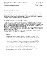
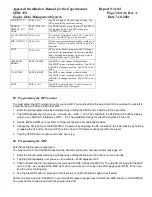
LOP DFLT? N 

YES 

 NO 

Tap YES to make LOP your default setting.  Tap 
NO to keep ROP your default setting. 

REMOTE 
DISPLAY I/O? 
NONE 

NEXT, EXIT OR 
EDIT 

Tap NEXT to move to next function. Tap EXIT to 
exit program mode.  Tap EDIT to change to 
“OUTPUT TO REMOTE”. 

CO  GUARDIAN? 

YES 

 NO 

To activate CO Guardian select YES.  Tap SAVE 
to save.  Tap NEXT to go to the next item.   

FDR OUTPUT? Y  YES 

 NO 

Allows export of recording instead of recording in 
memory. Tap SAVE to save or NEXT to go to the 
next item. 

END?  

YES 

 NO 

YES exits the Factory program mode. NO brings 
you back to the beginning of the Factory program 
mode.  Holding both buttons 1&2 will get you to 
Airframe Hobbs and TACH TIME. 

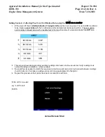
AIRFRAME 
HOBBS 

NEXT OR EDIT 

Tap EDIT to enter/change Airframe Hobbs. 

Tap DIGIT to move through each digit.  Tap PLUS 
or MINUS to change the value.  Tap SAVE to save 
value. 

TACH TIME 

NEXT OR EDIT 

Tap EDIT to enter/change Airframe Hobbs. 

Tap DIGIT to move through each digit.  Tap PLUS 
or MINUS to change the value.  Tap SAVE to save 
value. 

END? 

EXIT 

 NO 

Tap EXIT to restart the unit.  Tap NO to start at 
Airframe Hobbs/Tach Time again. 


29.


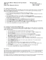
Programming the HP Constant 

You must adjust the HP Constant once for your aircraft. You must perform this adjustment in the air while the aircraft is 
in flight between 5,000 and 8,000 feet MSL. 

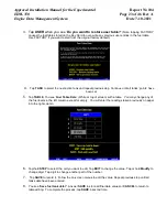
1.  Enter the pilot program mode by simultaneously holding the STEP and LF buttons for five seconds. 

2.  Tap STEP repeatedly until you see—for example— HPC =   I25. Then hold both the STEP and LF buttons display 

until you see ADJUST, followed by HPC=   I25. The adjustment range for the HP Constant is 45 to 180. 

3.  Set the MP and RPM per your POH to 70 percent power. Let conditions stabilize.  

4.  Change the HP reading on the EDM-350 to 70 percent by adjusting the HP constant in the lower display by holding 

or tapping the LF button. Percent HP should be close to 100 percent during takeoff at sea level. 

5. 

Tap the STEP button to proceed to the next step.


30.


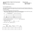
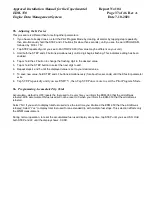
Programming the MAP 

Sets the manifold pressure calibration.  

You may need to correct the MAP based on the altimeter setting at a sea level airport (see page 27). 

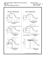
1.  Enter the pilot program mode by simultaneously holding the Step and LF buttons for five seconds. 

2.  Tap Step/OK repeatedly until you see—for example – MAP adjustment 0.0 . 

3.  Then hold both the first two buttons until you see ADJUST, followed by MAP+0. The adjustment range for the MAP 

is ±3.0 in Hg.  As you adjust the MAP up or down you will see a change in the MAP gage under RPM.   When you 
see the correct setting stop. 

4.  Tap the Step/OK button to proceed to the next step or hold both buttons again to exit setup. 

Do this one time and only if the MAP on your manifold pressure gauge doesn't match the MAP shown on the EDM-960 
You must do this on the ground with the engine turned off. 
.


Содержание EDM-350

Страница 1: ...________________________________ 24 21 GPS Interface _________________________________________________________________________________ 24 22 Manifold Pressure MAP Sensor __________________________________________________________________ 24 23 RPM Sensor installation _________________________________________________________________________ 25 24 EDM 350 Specifications and Limitations ______________...

Страница 2: ...u will not be able to access this K factor Determine the locations of all holes before drilling to ensure that nothing interferes with the probe clamp clamp screw or wire Provide service loops at the instrument so that it can be moved for maintenance or troubleshooting Thermocouple wire length is not critical Trim to required length allowing for service loops at the engine so that probes can be sw...

Страница 3: ...the aircraft at all times 4 Improper Calibration If the EDM 350 has not been properly calibrated it will not display accurate fuel levels in the tanks It is important you verify the accuracy of the EDM 350 Always crosscheck your measured fuel levels in the tanks with the readings on the EDM 350 before each flight 5 Poor Connections Poor connections between the wires leading from the EDM to the fue...

Страница 4: ...rosscheck the fuel levels displayed on the EDM 350 with your flight plan at each leg of the flight or every 30 minutes whichever happens first If there is a discrepancy land the aircraft at the nearest airport and verify the fuel levels Discrepancies should be taken seriously 5 New Pilot or Owner of the Aircraft If there is a new pilot or owner of the aircraft it is the previous aircraft pilot own...

Страница 5: ...n hg Engine Cylinder Head Temp CHT2 xxx o F Engine Oil Temperature O T xxx o F Engine Oil Pressure O P xxx o F Fuel Pressure F P xx PSI Fuel Flow to engine F F xx x GPH Comp Discharge Temp CDT xxx o F Turbine inlet Temp Left side TIT L xxxx o F Turbine Inlet Temp Right side TIT R xxxx o F Single Turbine Inlet Temp TIT xxxx o F Exhaust Gas Temp EGT2 xxxx o F Shock Cooling of CHT CLD xx o MIN Differ...

Страница 6: ...cular flashing alarm acronyms If another function has also reached its limit that label will then begin to flash The pilot should continue to monitor the affected parameters as he would if a conventional analog display had reached a limit The bar graph functions of CHT EGT and TIT remain displayed for easy reference should one of these limits be reached Alarm hierarchy is shown in the table below ...

Страница 7: ...Approved Installation Manual for the Experimental Report No 104 EDM 350 Page 7 of 46 Rev A Engine Data Management System Date 7 10 2021 EDM 350 Display ...

Страница 8: ...al for the Experimental Report No 104 EDM 350 Page 8 of 46 Rev A Engine Data Management System Date 7 10 2021 EDM 350 system mounts in a 3 125 inch diameter instrument panel hole Remote Alert Light comes with the placard Engine ...

Страница 9: ...ter hole Mounting bracket for the EDM 350 EDM 350 Model Mounts in a standard 3 1 8 instrument hole First place the mounting bracket on the instrument and tighten the clamp hex screw until you can just remove the instrument from the bracket The Mounting bracket is then placed behind the instrument panel hole and screwed 6 32 x screws in place using the existing holes Three screws should be used lea...

Страница 10: ...nder P3 790422 RPM MAP Oil pressure P4 700708 Serial data to GPS Serial data from GPS Fuel flow transducer P5 790723 Fuel Pressure Fuel Level Resistive and Capacitive Amps RAD 790749 Category 5 jack and cable for RAD Remote Alarm Display Route the wires from the connectors through the firewall using rubber grommets and flame retarding silicone Use an existing hole if possible All wires must be rou...

Страница 11: ...her a 14 or 28 volt electrical system The Avionics Bus power wire to the EDM should be 20ga copper A 5 amp circuit breaker is required Connect the EDM ground wire to the engine block For lighting no connection to the aircraft dimmer system is required because the instrument dims automatically with reductions in ambient light Required power for the 350 is 1 0 amp at 14vdc 9 Probe Wiring When cuttin...

Страница 12: ...e existing holes in the exhaust stack are 1 8 to 1 4 in diameter If no hole exists it will require the drilling of a 1 8 diameter hole and ream to fit It is important that each probe be mounted the same distance from its exhaust stack flange A nominal distance of 2 to 4 inches from the exhaust flange is recommended If the recommended distance is impractical because of obstructions slip joints or b...

Страница 13: ...art number from the aircraft manufacturer If you choose to use only the EDM 350 TIT display you may remove the factory installed TIT indicator and leave the TIT probe installed Connect the JPI wire marked TIT directly to the probe noting color polarity The TIT probe should now have only the JPI leads attached to it No calibration of the EDM 350 is necessary 11 Cylinder Head Temperature CHT Probe I...

Страница 14: ...lve Remove the screw plug now in that hole and screw the CRB probe into the carburetor throat No drilling or machining of the carburetor is necessary 14 Oil Temperature Probe Installation The sensor port is a standard 5 8 18 thread for both the Continental and Lycoming engines Probe PN 400509 is a complete assembly using type K thermocouple wire red yellow Connect the wire marked oil temperature o...

Страница 15: ...lied as depicted in the drawing below Use Aluminum Clamps MS21919WDG25 or WDG14 to mount the pressure sensor to engine mount structure or firewall Do not mount the sensor s directly to the engine Connect the other end of the hose to the existing pressure line Later you will connect the pressure sensor to the three pressure sensor wires through the supplied 3 pin connector i2s sensor PN 159935A Nor...

Страница 16: ...talled between the master contactor and the main bus in which case it will be in the ammeter configuration showing battery charge and discharge Be sure that the positive side of the shunt is connected to the main bus in the ammeter configuration The alarm will be triggered by a discharge condition BATT Master switch Starter Starter solenoid Master switch contactor Bus F G B external shunt Ammeter ...

Страница 17: ...lent PN 201 A NA 201 B 680501 680600 201 C NA 231 680503 Before connecting any hoses to the transducer thoroughly clean them and insure they are free of any loose material Never pass air pressure through the transducer or use Teflon tape pipe cement damage will occur Use only steel fittings supplied never use aluminum fittings on transducer Additional fittings are available from JPI Remove the tra...

Страница 18: ...type senders are uncommon in certified aircraft JPI supports this interface The P5 harness has two 3 conductor cables labeled LEFT TNK and RT TANK that are connected directly to the left and right senders See the drawing below for basic connection information only right tank shown for illustration purposes Final route the LEFT TNK and RT TANK cables as necessary then crimp the female contacts onto...

Страница 19: ...on Manual for the Experimental Report No 104 EDM 350 Page 19 of 46 Rev A Engine Data Management System Date 7 10 2021 Example harness arrangement for an aircraft with resistive output senders Resistive Harness PN 790719 3 ...

Страница 20: ...uge In some cases the Pennycap convertor box alternately monitors two tanks per wing controlled by cockpit selector switch positions This is typical for Cessna s having 4 selectable tanks The EDM can interface to this system with the addition of the interface hardware PN 791802 NOTE This drawing is sent with the kit if applicable and is accurate for most models of the Pennycap system however it is...

Страница 21: ...ding is always taken with unusable fuel in the tank Example of a completed table for LEFT tank LEFT F 39 0 GAL 1907 29 3 GAL 1431 19 5 GAL 1145 9 8 GAL 971 E 0 0 GAL 685 2 This screen shown below provides real time readings of all active fuel level sensors Verify readings look normal Reading are arbitrary whole numbers 3 Now add fuel as needed to match the required volume for a particular point Cy...

Страница 22: ...l Level Calibration Data The Fuel Table Editor is a spreadsheet type format allowing you to easily see the volume and related calibration values side by side You can easily navigate through the cells to enter values 1 With power off hold in Button 3 Button 1 being far left and then turn on power Wait until you see Do you agree with the disclaimer Tap YES if you agree and wish to continue 2 Tap YES...

Страница 23: ... have been set 5 Tap TABLE You see Fuel Table Data White at top of screen with a table You may change any of the fuel levels in the left column except for empty You will enter the readings taken previously on paper into the right column 6 Tap hold STEP to select the cell you want to edit Tap EDIT to change the value Tap or hold Modify to change digit Tap digit to change another part of the number ...

Страница 24: ...ou see FACTORY At this point you will see MAIN XX adjust with the Plus and Minus buttons Tap next for AUX XX and adjust Tap button twice to finish and save 21 GPS Interface Use the J4 connector harness 700708 labeled RS232 OUT TO GPS white and RS232 IN FROM GPS gray Refer to the Manufactures GPS manual for the required pin connections on the GPS 22 Manifold Pressure MAP Sensor Screw a AN816 4D fla...

Страница 25: ...9264 2200 0 9230 2300 0 9196 2400 0 9162 2500 0 9129 2600 0 9095 2700 0 9062 2800 0 9028 2900 0 8995 3000 0 8962 3100 0 8929 3200 0 8896 3300 0 8863 3400 0 8830 3500 0 8798 3600 0 8765 3700 0 8733 3800 0 8700 3900 0 8668 4000 0 8636 4100 0 8604 4200 0 8572 4300 0 8540 4400 0 8508 4500 0 8477 4600 0 8445 4700 0 8414 4800 0 8382 4900 0 8351 5000 0 8320 5100 0 8289 5200 0 8258 5300 0 8227 5400 0 8196...

Страница 26: ...Approved Installation Manual for the Experimental Report No 104 EDM 350 Page 26 of 46 Rev A Engine Data Management System Date 7 10 2021 ...

Страница 27: ...oad or charge discharge Load NON TSO 20 HC 120 of HP NON TSO 21 Fuel Level Resistive Capacitive TSO 55 22 Low fuel 10 Gal 23 Low time 45 Min 24 Main tank 75 gallons 25 Aux tank 0 26 GPS set at GARMIN 27 Diff 500 degrees TSO C43 28 CLD 60 degrees per minute TSO C43 29 Amps limit 100 amps NON TSO 30 Record time 6 sec intervals NON TSO 31 Hobbs on at 1000 RPM NON TSO This is normal due to extremely l...

Страница 28: ...cedures see Aircraft Pilot Operating Handbook Verify that the EDM 350 is operating normally and there are no bad probes or alarm messages Set the frequency and audio panel to listen to that radio Loud buzzing humming is considered unusual noise in the context of these tests also the OBS needle should not move Should any EMI noise be found that is attributed to the EDM 350 system it must be correct...

Страница 29: ...ressurized 1 1 RPM one of P N 420815 1 2 Non Pressurized 1 1 RAD P N 790749 1 1 26 1 Component Parts List for EGT KIT 1280 TIT KIT 1200 Probe 1 Thermocouple type K probe PN M 111 1 Stainless Steel Clamp Thimble 1 Stainless Steel Exhaust Seal Washer 1 Stainless Steel Screw Type Clamp 2 Ring Terminals 2 Screws and nuts 6 32 X 1 4 1 Fiberglass tube 3 8 x 5 26 2 Component Parts list for CHT KIT 1260 1...

Страница 30: ...mponent Parts list for ampere shunt Kit 1300 1 P N 159920 100 amp shunt 2 Ring Terminals 26 10 Component Parts list for Fuel Flow Transducer 1 fuel flow transducer 201 or 231 PN 700900 1 2 8 inches of 1 5 dia fire sleeve 1 3 pin Molex connector housing 3 female pins Molex 2 AN816 4 4 fittings Continental or AN816 4 6 Lycoming 26 11 Component Parts list for MAP sensor KIT 1440 1 P N 159934A Manifol...

Страница 31: ...hrough these values Comments PROGRAM Stays on for two seconds FUEL N FILL N Tap LF to change fuel status Exits program mode when done SOFTWARE INFO INFO Software PN Version RATE 4 0 9 Index rate pause time in seconds in the Automatic Mode 0 disables the Automatic Mode TRIP USED YES NO NO When Refuel mode used on EDM total fuel used is reset to 0 YES accumulate total fuel used rather than reset to ...

Страница 32: ...e number the better the dampening effect Fuel pump pulses TIME 18 23 59 00 00 00 23 59 59 Hold NEXT and button 2 for 5 seconds until you see ADJUST Use Hours Minutes Seconds to adjust Tap SAVE to save changes Tap NEXT to skip to next item DATE 05 14 09 01 01 00 12 31 99 Hold NEXT and button 2 for 5 seconds until you see ADJUST Use Month Day Year to adjust Tap SAVE to save changes Tap NEXT to skip ...

Страница 33: ...RMS YES NO Tap YES to enable pre alarms for HI EGT HI CHT HI OIL T LOW TANK LAST FLIGHT NO EDIT Tap EDIT to adjust PLUS or MINUS the flight number Tap SAVE to save change Allows setting the last flight no Used during a factory reset continues numerical order AVERAGE CRUISE RPM 2400 NEXT Tap EDIT to adjust Tap PLUS or MINUS to adjust then SAVE to save the change Average cruise is based on a percent...

Страница 34: ...air while the aircraft is in flight between 5 000 and 8 000 feet MSL 1 Enter the pilot program mode by simultaneously holding the STEP and LF buttons for five seconds 2 Tap STEP repeatedly until you see for example HPC I25 Then hold both the STEP and LF buttons display until you see ADJUST followed by HPC I25 The adjustment range for the HP Constant is 45 to 180 3 Set the MP and RPM per your POH t...

Страница 35: ...he gauges follow these steps 1 Enter Pilot Program Mode by holding the STEP and LF buttons for 5 seconds 2 When the EDM enters Program Mode tap the button labeled NEXT until END Is displayed in the scanner message area 3 Again hold the STEP and LF buttons until the EDM enters Factory Program Mode 4 After Factory is displayed in the scanner message area tap the NEXT button until CUSTOMIZE DISPLAY i...

Страница 36: ...rocedure to fine tune the K factor 1 Make at least three flights of about two to three hours each Note the actual fuel used as determined by topping the tanks and the EDM 3500 calculation of the fuel used for each flight USD Flight Fuel USED shown by EDM total tank REM Actual fuel used by topping tanks 1 2 3 Total 2 Total the EDM 350 calculated fuel used and the actual fuel used 3 Record the curre...

Страница 37: ...e next digit to edit 6 Repeat steps 4 and 5 until the displayed value is set to your desired value 7 To save new value hold STEP and LF buttons simultaneously for about five seconds until the K factor parameter exits 8 Tap STEP repeatedly until you see END Y then Tap STEP once more to exit the Pilot Program Mode 36 Programming Accumulate Trip Total Accumulate default is OFF resets the fuel used to...

Страница 38: ...ean without stopping Lean more rapidly PEAK NOT FOUND DURING LEANFIND Lean Find not activated or stopping while leaning Lean at the speed of approximately 10 F per second OFF SCALE EGT COLUMNS TOO HIGH OR LOW Off scale EGT column readings EDM in the Normalize view blue EGT scales Return to Standard mode by holding the LF button FIRST CYLINDER TO PEAK IS NOT THE HOTTEST The first to cylinder peak i...

Страница 39: ...t be reflected in the HOBBS meter Return unit to factory HOBSBAD The HOBBS data has been corrupted Return unit to factory HANGCFG HANGCAL Internal system errors Return unit to factory 38 GPS Interface Diagnostics Problem Situation Correction Measurements xxx REQ XXX RES AND XXX MPG are all missing from the scan No communications from GPS receiver to EDM No connection or aircraft GPS is off NO COM ...

Страница 40: ...rt No 104 EDM 350 Page 40 of 46 Rev A Engine Data Management System Date 7 10 2021 43 Connector Pin Assignments on EDM J1 through J5 Rear view of EDM 350 Showing Connector Locations 6 1 9 5 9 1 15 8 14 1 25 13 14 1 25 13 P3 P1 P2 P4 9 1 15 8 P5 Alert Light ...

Страница 41: ...el 5 red 6 yel 14 red 15 yel 16 red 17 yel 18 red 19 gray 12 Remote temperature voltage alarm light option red 13 black 25 OAT yel 1 red 2 J1 FOR 7 8 and 9 cylinder installations yel 3 red 4 Aircraft engine ground lead 12 or 24 vdc power lead OIL temperature sensor TIT 1 sensor Carb temperature sensor yel 5 red 6 yel 22 red 23 yel 20 red 21 yel 18 red 19 gray 12 Remote temperature voltage alarm li...

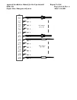
Страница 42: ...anagement System Date 7 10 2021 J2 yel 1 red 2 yel 3 red 4 yel 5 red 6 yel 14 red 15 yel 16 red 17 yel 18 red 19 yel 9 red 10 yel 7 red 8 yel 11 red 12 yel 24 red 25 yel 22 red 23 yel 20 red 21 CHT sensors x4 or x6 EGT sensors x4 or x6 CHT 1 EGT 1 CHT 6 CHT 5 CHT 4 CHT 3 CHT 2 EGT 6 EGT 5 EGT 4 EGT 3 EGT 2 ...

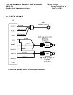
Страница 43: ...te 7 10 2021 44 J3 RPM MP Oil P J3 Green 6 Green 8 9 NC green 1 black 2 red 3 black 7 red 4 black 5 1 2 3 RPM sig RPM ground RPM power RPM 420815 1 or 2 MAP i2S 0 5v PN 159934A 0 30 psia Oil P i2s 0 5v PN 159936A 0 150 psi power ground signal ground signal Oil P OIL P MAP J 3 Harness with i2s Oil and manifold pressure sender ...

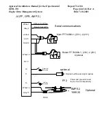
Страница 44: ...IN OUT Main FF 700900 1 201 2 231 White 1 Gray 2 white 4 red 5 black 6 NC 9 White 12 10 11 13 White 14 Gray 15 Remote fuel flow alarm light option IN OUT FF2 Power and ground connect to pins 5 and 6 respectively 5 6 Right low fuel switch Left low fuel switch AMPS 2 159920 J4 FF GPS AMP 2 Return FF 700900 1 201 2 231 Optional Optional optional Serial communications FUSE ...

Страница 45: ...white Aux Pwr IN optional 11 Red Sig 1 Sig 2 5vdc Green sig 2 pin 2 White Sig 1 pin 1 Gnd X2 Blk pin 3 Ground at Sender Sig 3 Sig 4 Gnd 5 vdc Signal Sig 1 Sig 2 Sig 4 Sig 3 SINGLE L MAIN R MAIN FUEL TANK CONFIGURATION PN 790723 Fuel Press Sig iFuel Pressure 0 50 PSIG PN 159935A or 0 100 PSID PN 159938 Differential Pressure Electrical Connections are the same for both PN 159935A or 159938 Ground Po...

Страница 46: ...Approved Installation Manual for the Experimental Report No 104 EDM 350 Page 46 of 46 Rev A Engine Data Management System Date 7 10 2021 ...

Отзывы: