J.E. Adams 8670-5WB Скачать руководство пользователя страница 13

8670-5WB Manual – 10/2006 

13


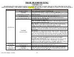
Figure 7:   Infitec timer setup 

Figure 7 shows an Infitec timer set for 2 coins to start and a total run time of 

240 seconds (4 minutes). 


TIMER SETUP – INFITEC TIMERS 


The Infitec timer has two adjustable settings:  Total run time (in seconds) 
and number of coins to start.   
 

Total run time: 
Total run time

 is the amount of time the unit will run once activated and 

can be set from 

1 second

 to

 1023 seconds (17 minutes and 3 seconds)

 in 

increments of 1 second by turning on the correct switches until their 
values equal the desired time

.

  Refer to Tables 1 and 2 (pages 14-15) for 

standard timer and coin settings.  For custom settings, follow the steps 
below: 
 

1.


 Figure the total time your vac will run (in seconds).  This is your 

total run time

.  Round up or down as desired. 

2.


Subtract the largest value switch (initially 512) from your 

total run 

time

.  

a.


If the resulting number is zero

, move the switch to the 

“on”


position and set all remaining un-set switches in the 

“off”


position.  Your timer is now set. 

b.


If the resulting number is positive

, move the switch into the 

“on”

 position.  Using the resulting number as your new 

time 

per coin

, repeat step 2 with the next largest switch value. 

c.


If the resulting number is negative

, set the switch in the 

“off”

 position and repeat step 2 using the next largest switch 

value. 


Coins to start:


Coins to start

 is the amount of coins needed to activate the timer and 

can be set from one to 15 coins in increments of one coin.  Refer to Table 
1 (page 14) for switch settings. 


Содержание 8670-5WB

Страница 1: ......

Страница 2: ...nting and Routing Detail 8 o Figure 3 Electrical Installation Detail 9 o Figure 4 Cabinet and Base Dimensions 10 Timer setup 11 15 o SSAC Setup 11 o IDX Setup 12 o Infitec Setup 13 o Timer Settings Chart 14 o Typical Timer Settings 15 Programming the Remote Start System 16 Maintenance 17 Parts Breakdown 18 20 o 8670 5WB 18 o 8778A 1 19 o 22002 51A 20 Schematics 21 o S8670 5WB 21 Troubleshooting 22...

Страница 3: ... can Key number can be found on the tag that comes attached to the keys There may be more than one key number depending on unit Please keep this information with your records MODEL _________________________________________ SERIAL _________________________________________ KEY NUMBER S _________________________________ DATE PURCHASED _______________________________ DISTRIBUTOR ______________________...

Страница 4: ...AC 60Hz 14 AMPS 1 5 HORSEPOWER ONE CYLINDER ONE STAGE OIL LESS SCFM PSI 6 0 5 20 4 1 40 3 1 90 2 9 100 2 1 125 MAX PSI TEMPERATURE RANGE 10 DEGREES F TO 100 DEGREES F MOTOR 1 5 HP 1725 RPM CAPACITOR START NEMA 56 FRAME AUTOMATIC THERMAL OVERLOAD NO LUBRICATION REQUIRED ON MOTOR OR COMPRESSOR ...

Страница 5: ...TIME INCORRECTLY GENERAL MECHANICAL ALL DIMENSIONS IN DRAWINGS ARE IN INCHES MOUNTING STUD SIZE 3 8 X 16 UNC X 1 4 MINIMUM CONCRETE REQUIRED AROUND MOUNTING STUD 18 MINIMUM PAD RECOMMENDED FOR BUMPER CLEARANCE FOR GASOLINE DISPENSING LOCATIONS A MINIMUM 18 HIGH PAD ABOVE THE DRIVEWAY 20 FOOT HORIZONTAL CLEARANCE FROM THE EXTERIOR ENCLOSURE OF ANY GASOLINE DISPENSING PUMP ELECTRICAL SERVICE Dedicat...

Страница 6: ...DO NOT install the cover at this time 4 Mount cabinet to base securely as shown in Figure 2 using only the four 5 16 18 X bolts DO NOT install the 20 X bolts at this time 5 Using Figures 2 3 install electrical and water services to the unit and run air and water lines to the inputs of their respective hose reels Air line should run between the output of the unloader valve and the input of the air ...

Страница 7: ...8670 5WB Manual 10 2006 7 Figure 1 Installation footprint for 6025 hose reel base ...

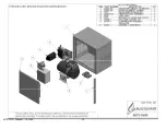
Страница 8: ...8670 5WB Manual 10 2006 8 Figure 2 Mounting and routing detail ...

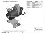
Страница 9: ...8670 5WB Manual 10 2006 9 Figure 3 Electrical installation detail ...

Страница 10: ...8670 5WB Manual 10 2006 10 Figure 4 Cabinet and hose reel base dimensions ...

Страница 11: ...mer and coin settings For custom settings follow the steps below 1 Figure the total time your vac will run in minutes and divide that number by the number of coins to start This is your time per coin Round up or down to the nearest tenth of a minute 2 Subtract the largest value switch initially 6 4 from your time per coin a If the resulting number is zero move the switch to the on position and set...

Страница 12: ...r using Table 1 ignore settings for switches 1 and 512 For custom settings follow the steps below 1 Figure the total time your vac will run in seconds and divide that number by the number of coins to start This is your time per coin Round up or down to the nearest even number 2 Subtract the largest value switch initially 256 from your time per coin a If the resulting number is zero move the switch...

Страница 13: ...ow the steps below 1 Figure the total time your vac will run in seconds This is your total run time Round up or down as desired 2 Subtract the largest value switch initially 512 from your total run time a If the resulting number is zero move the switch to the on position and set all remaining un set switches in the off position Your timer is now set b If the resulting number is positive move the s...

Страница 14: ... 0 8 48 sec 0 9 54 sec 1 0 1 1 1 2 1 3 1 4 1 5 1 6 1 7 1 8 1 9 2 0 2 5 3 0 3 5 4 0 4 5 5 0 5 5 6 0 6 5 7 0 7 5 8 0 8 5 9 0 9 5 10 0 0 1 x x x x x x x x x x x x x x x x x x 0 2 x x x x x x x x x x x x x x x x x x 0 4 x x x x x x x x x x x x x x x x x 0 8 x x x x x x x x x x x x x x x x 1 6 x x x x x x x x x x x x x x 3 2 x x x x x x x 6 4 x x x x x x x x 1 2 3 4 5 6 7 8 9 10 11 12 13 14 15 1 x x x ...

Страница 15: ...N 50 4 1 2 MIN 2 4 8 256 50 5 MIN 2 4 16 128 50 5 MIN 0 1 0 8 1 6 50 5 MIN 4 8 32 256 50 5 1 2 MIN 2 4 32 128 50 5 1 2 MIN 50 5 1 2 MIN 2 8 64 256 75 2 MIN 8 32 75 2 MIN 75 2 MIN 8 16 32 64 75 2 1 2 MIN 2 16 32 75 2 1 2 MIN 75 2 1 2 MIN 2 4 16 128 75 3 MIN 4 8 16 32 75 3 MIN 0 2 0 8 75 3 MIN 4 16 32 128 75 3 1 2 MIN 2 4 64 75 3 1 2 MIN 75 3 1 2 MIN 2 16 64 128 75 4 MIN 16 64 75 4 MIN 75 4 MIN 16 3...

Страница 16: ...circuit board in place 3 Press and release the Learn Code Button LED indicator will blink at a rate of two times per second 4 Press the Transmitter Button once The indicator light should now be on continuously 5 Press the same Transmitter Button again The indicator light should now turn off The remote start system should now be programmed Note You must perform steps 3 5 within 30 seconds If the LE...

Страница 17: ... on top of valve and remove coil cover and coil Then using a flat head screwdriver remove the piston housing Clean out any debris on the piston and in the piston housing and reassemble the valve Clean the outside portion of the cabinet with a stainless steel polish DO NOT use any abrasive cleaners steel wool or any kind of brush to clean the exterior Doing so could possibly scratch or damage the f...

Страница 18: ...8670 5WB Manual 10 2006 18 ...

Страница 19: ...8670 5WB Manual 10 2006 19 ...

Страница 20: ...8670 5WB Manual 10 2006 20 ...

Страница 21: ......

Страница 22: ...move the wires leading to the timer from the coin mech and tap them together one time for each coin necessary to start the timer If machine starts replace the coin mech Remote Starter Test transmitter batteries and replace if needed Remove receiver cover and verify proper voltage across terminals 1 and 3 24VAC If proper voltage is present and transmitter batteries are good follow instructions to p...

Отзывы: