P
RODUCT INFORMATION
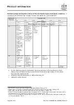
3.5.3. Explosion protection classification
Your product
PROFI 3 TI
is marked according to
EC directive 2014/34/EU and DIN EN 1127-1 as
follows:
II 3G Ex h IIB T4 Gc X
II 3D Ex h IIIB T130
◦
C Dc X
II 2G Ex h IIA T4 Gb X
II 2D Ex h IIIA T130
◦
C Db X
The additional marking “X” refers to the explosion
protection in the operating instructions.
Additional label “X”:
This mark does not allow use
in the event of light alloy metal or other impact
sensitive dusts. The permissible ambient tempera-
ture range is from -20
◦
C (-4
◦
F) to +40
◦
C (+104
◦
F).
Additional label “X”:
This mark does not allow use
in the event of light alloy metal or other impact
sensitive dusts. The permissible ambient tempera-
ture range is from -20
◦
C (-4
◦
F) to +40
◦
C (+104
◦
F).
For more information about explosion protection
,
→
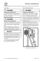
3.5.4. Vane motor
The vane motor (
,
→
Figure 4) consists of a cylin-
der liner
(1)
with two lateral bearing washers and
an inner rotor
(2)
.
The rotor is mounted eccentrically in the cylinder
liner and is provided with slots
(3)
for holding the
slats
(4)
.
The slots can move freely and are on the inner
wall
(5)
of the cylinder liner. Two slots form a
chamber
(6)
.
The incoming compressed air creates a greater
force at the leading larger slot surface
(4.1)
than at
the following smaller slot surface
(4.2)
. The rotor’s
torque results from the difference in force.
The compressed air can again escape when pass-
ing through the outlet opening
(7)
Lubricant cham-
bers
(8)
are arranged between the vane slots of
the rotor. They ensure a continuous motor lubrica-
tion (not applicable for mini).
The arrows in the illustration indicate the direction
of rotation of the rotor and the corresponding path
of the compressed air.
Figure 4: Functioning of the compressed air vane
motor
Page
14
of 60
Doc.-No.: VA053957-40-OM-EN-0720-60-2


