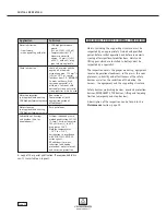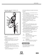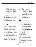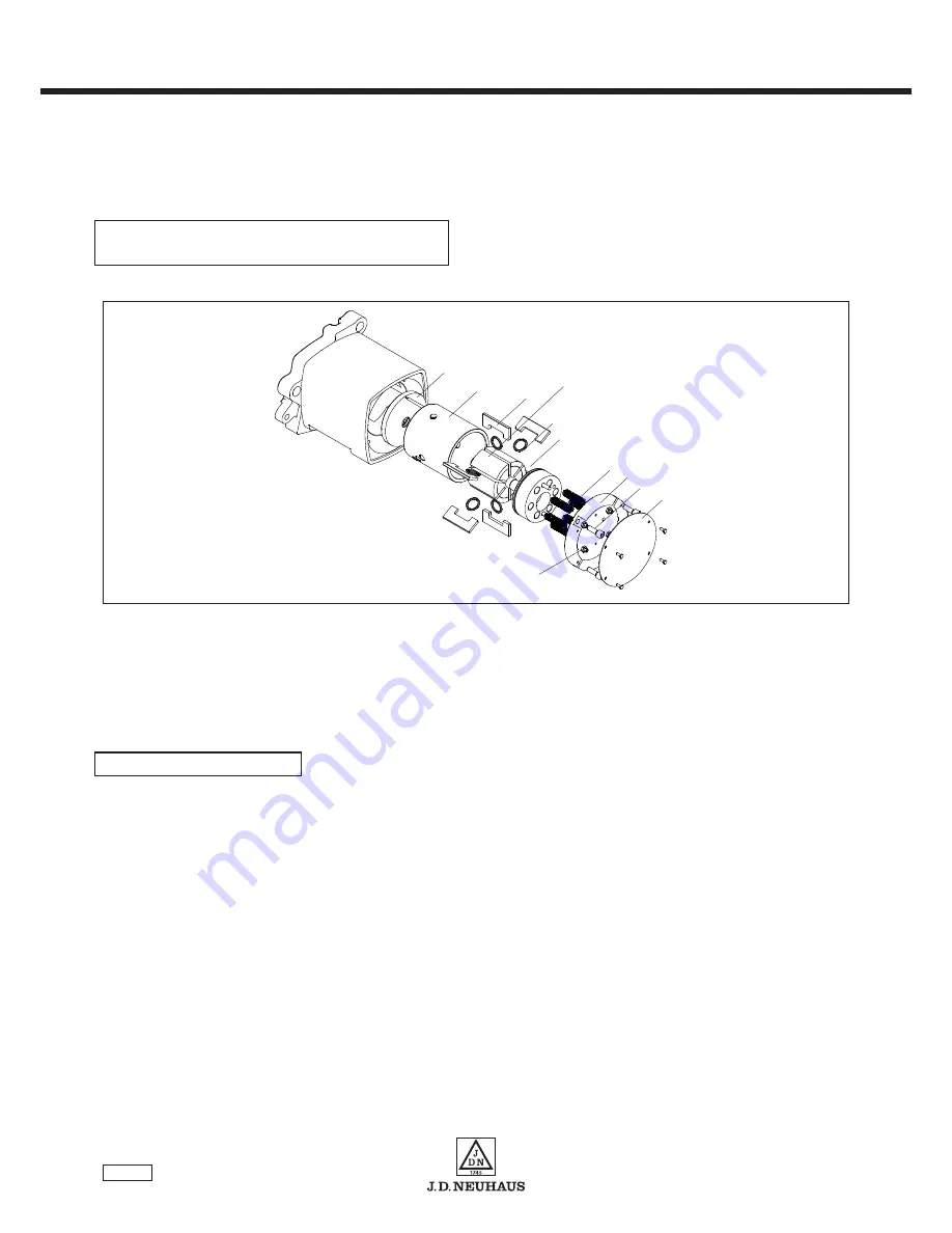
The braking action is applied at the lateral surfaces of
the rotor. The rotor is pressed via spring force from the
cover side of the motor against a brake disc located on
the opposite side by means of a brake piston.
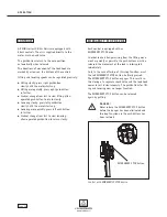
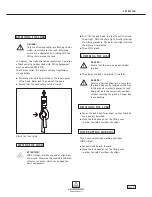
Remove the nameplate
1
.
Release the lock nuts
14
of the adjusting bolts
13
(4 screws).
Screw in the adjusting bolts
13
to the stop in the
cover; do not tighten.
Then screw back the adjusting bolts
13
45° from
the stop, hold and lock with the nuts
14
.
Attach the nameplate.
R E M O VA L
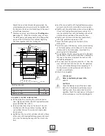
Proceed as follows when removing the brake disc and
brake piston:
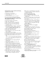
Disconnect the hoist from the main air supply.
Unscrew the nameplate
1
.
Remove the cover bolts
2
behind the nameplate and
detach the cover
3
(when the cover bolts are removed,
the tension of the brake springs
4
is fully released).
Remove the springs
4
.
Remove the brake piston
7
from the cylinder liner
8
.
Pull out the rotor
9
, collecting the vanes
10
and
starting aids
11
.
N O T E
If you only wish to replace the vanes with the starting
aids, please continue with the section ˝Checking for
vane wear˝.
Pull out the cylinder liner
8
.
Remove the brake disc
12
.
Check the brake disc
12
and brake piston
7
for wear
and damage, replace if necessary. The circular wear
pattern must not be deeper than 0.2 mm.
The extremely low-wear braking material will not reach
the wear limit of 0.2 mm within the design-dependent
service life of the hoist, under intended use.
A D J U S T I N G T H E B R A K E
R E P L AC I N G B R A K E D I S C , B R A K E P I S T O N
A N D VA N E S / M O T O R I N S TA L L AT I O N
powered by air !
M A I N T E N A NC E
Page 36
Replacing brake discs, brake piston and vanes / Motor installation
12
8
10
9
11
7
4
3
2
1
13/14
Содержание JDN mini 1000
Страница 47: ...powered by air NOTES Page 47 ...

