


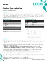


Capabilities
The ResidualHQ controller comes standard with Modbus RTU (RS-485) serial communication capabilities. The controller
operates as a slave device, supporting the following function codes: Read Holding Registers (0x03), Write Single Holding
Register (0x06), and Write Multiple Holding Registers (0x10). Read capabilities are always available, while Read/Write is
access-protected and must be enabled locally in under
Configure > System > Remote Enable
. More information relating to
the Modbus protocol and specification can be found at www.modbus.org.
Configuration
Modbus-specific parameters can be found locally at the HMI under
Configure > System.
•
If
Modbus RTU ID
(slave address) is changed,
Modbus RTU Reload
must be pressed to process the identification
change.
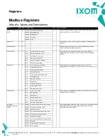
Values provided are unsigned 16 bit integers, with values ranging from 0 to 65535. In order to represent floating point
numbers (
ex. 2.95
) a scaling factor is used.
•
Read values should be divided by the Scale given in the Modbus Parameter Tables (
ex. 295 / 100 = 2.95).
•
Likewise, written values should be multiplied by the Scale prior to sending the command (
ex. 2.95 * 100 = 295
).
In certain instances registers are reported as hexadecimal (denoted by 0x) values to represent status information.
Additionally, certain registers indicate relevant information through bit positions.
•
For example, a value of 0x0070 (decimal 112) represents a Standby status in several modes of operation.
•
Similarly, Bit 3 may represent a valve position, or area-specific error recognized by the system.
•
Boolean values are reported as 16 bit integers where: True == 0x0001 and False == 0x0000.
If an invalid or out-of-range write value is attempted, the command will be ignored and the register will retain the previous
value.
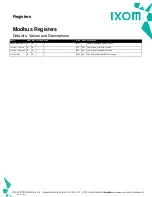
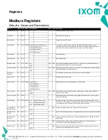
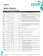
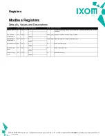
Register-specific information may be found in the Modbus Parameter Tables.
Interface (DB9 female)
Pin
Pin
Description
Description
1
Logic or communication ground
2
N/A
3
TxD+ (B)
4
N/A
5
Logic or communication ground
6
+5VDC (240mA max.)
7
N/A
8
TxD- (A)
9
N/A
Communication Parameters
Setting
Setting
Value
Value
Baud Rate
19.2k (standard)
Bits/Byte
8
Parity
None
Stop Bits
1
Address Range (ID)
1-247
Left: Terminating device (bias ON)
Right: Non-terminating device (bias OFF)
©2022 IXOM Watercare Inc. | www.ixomwatercare.com | 866 - 437 - 8076 | [email protected]
Modbus
Modbus Communication
Interface and Diagnostics
10318_20220119
ControlManual_ResidualHQ_10380_20220809a - 20


