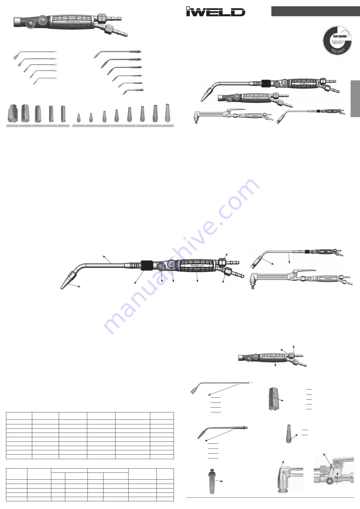
4 - Shank and Attachments
5IK302601
IWELD KOMBI 30 shank
Heating Attachments
Welding Attachments
Heating Nozzles
Welding Nozzles
5 - Frequent malfunctions
• Loose connection nut
- Loose connection nut (6) will not insure proper gas aspiration therefore the flashback danger will be
high.
• Incorrect nozzle selection for welding, cutting or heating process.
As a result of applying incorrect nozzle for welding, heating or cutting the flame will not be stable dur
-
ing the process. Choose the proper nozzle size always!
6 - Maintenance
• Repair and maintenance should be done by trained and authorized technician. Only original spare
parts should be used for repair. Producer declines all liability for damages, accidents caused by un
-
professional repairs.
• Torches must be controlled periodically. If any part, valves, nipples etc. are leaking, damaged or
simply are dirty from oil, the use of the equipment is strictly prohibited! Send the device to authorized
service partner for repair or inspection.
• Should you notice any internal or external leakage at the shank valves, at the nipples and nuts then
the gas supply must be closed immediately! Never retry to use the leaking components prior any pro
-
fessional inspection!
7 - Storing and transportation
• To protect your device from any possible damage during transportation store it always in its original
box.
• Shall you store your equipment for long time please make sure that all components are clean, and
dry. The storage area must be dry, clean and safe from dust sources.
8 - Cautions
• There shouldn’t be done any changes on torches without our company’s control and information.
• Improper use of the cutting torches may cause serious damages. They should be used by trained
staff only.
• Torches must be protected from accidentally crashes, falls, oil and another dirt sources.
• Torches and their attachments should be used respecting the markings.
• Attachments and nozzles on the heating and welding process must be selected according to in
needed heat values as shown in Table-1 and Table-2.
9 - Installation
• Welding attachment or heating attachment’s connection nut (6) must be screwed on the shank
tightly.
• As Regards of changing nozzles on welding attachment and heating attachment, welding or heat
-
ing nozzle (8-10) that are picked considering Table-1 or Table-2 must be installed to welding or heating
attacments (7-9) by using suitable wrench.
• Gas hose ( Ø6 mm) must be connected to installed welding or heating attachment hose connection
by using clip according to equipment which is used.
• When using welding, heating and cutting torches, flashback arresters must be used between hose or
flachback arrester that is suitable to torch on the system must be used.
Due to welding, heating and cutting torches are working with vacuum principle, shank
connection nut (6) must not be loose!
10 - Technical information tables
Table-1 Welding Attachments and Nozzles
Welding Nozzle
Order No.
Welding Attach
-
ment Order No.
Welding Capacity
Oxygene Pressure
and consumption
Acetylene Consumption
Heat Value
5IKVRG2010
5IK303610
0.2 -0.5 mm
2,5 bar - 85 (l/h)
0,25-0,35 bar - 85 (l/h)
8026 kj/h
5IKVRG2011
5IK303611
0.5 - 1 mm
2,5 bar - 95 (l/h)
0,25-0,35 bar - 105 (l/h)
9915 kj/h
5IKVRG2012
5IK303612
1 - 2 mm
2,5 bar -105 (l/h)
0,25-0,35 bar - 127 (l/h)
11992 kj/h
5IKVRG2013
5IK303613
2 - 4 mm
2,5 bar -125 (l/h)
0,25-0,35 bar - 150 (l/h)
14164 kj/h
5IKVRG2014
5IK303614
4 - 6 mm
2,5 bar -160 (l/h)
0,25-0,35 bar - 230 (l/h)
21718 kj/h
5IKVRG2015
5IK303615
6 - 9 mm
2,5 bar -220 (l/h)
0,25-0,35 bar - 280 (l/h)
26440 kj/h
5IKVRG2016
5IK303616
9 - 14 mm
2,5 bar -280 (l/h)
0,25-0,35 bar - 385 (l/h)
36355 kj/h
5IKVRG2017
5IK303617
14 - 20 mm
2,5 bar -390 (l/h)
0,25-0,35 bar - 500 (l/h)
47215 kj/h
5IKVRG2018
5IK303618
20 - 30 mm
2,5 bar -435 (l/h)
0,25-0,35 bar - 610 (l/h)
57602 kj/h
Table-2 Heating Attachments and Nozzles
Heating
Nozzle
Art. No.
Heating Attach
-
ment
Order No.
Oxygene
Propane (LPG)
Heat Value
Attach.
Lenght
Pressure
Consumption
Pressure
Consumption
87694721H
5IK303701
1-2 bar
4000-7000 l/h
0.5 bar
1000-2000 l/h
93700-187395 kj/h
420 mm
87694732H
5IK303702
1-2 bar
5900-12800 l/h
0.5 bar
1500-3200 l/h
93700-187395 kj/h
420 mm
87694743H
5IK303703
1-2 bar
8500-22900 l/h
0.5 bar
2200-5700 l/h
205890-534000 kj/h
490 mm
87694754H
5IK303704
1-2 bar
14200-28400 l/h 0.5 bar
3600-7100 l/h
337400-663865 kj/h
600 mm
87694765H
5IK303705
1-2 bar
17000-39700 l/h 0.5 bar
4300 -100000 l/h
403360-936975 kj/h
670 mm
KOMBI
30
Cutting and Welding Sets and Attachments
INSTRUCTION MANUAL
The device should be used by trained person after regarding this manual only.
1 - Sets and their specifications
• Both welding, heating and cutting processes can be executed with the shank (IK302601).
• The system is designed and manufactured according to EN ISO 5172 standard.
Welding
• Welding attachments are designed ergonomically by forming different flame sizes for oxy-acetylene
welding processes in different industrial areas. Spare welding nozzles are available to reduce your
maintenece cost.
Heating
• Heating attachments are designed to form large flame sizes for heating, burning and melting pro
-
cesses for different industrial areas where high temperature is needed. Oxy-propane flame temp-
erature is reasonably higher than air-propane mixture flame temperature. Spare heating nozzles are
availables also.
Cutting
• The cutting attachment is designed to answer different industrial sector’s oxy-fuel cutting needs.
The cutter that is designed for both acetylene, propane and natural gas is a state of the art tool. The
cutting attachment is very safe, however you have to pay special attention to use the proper fuel gas
specific cutting nozzle.
2 - Application
• Set the gas pressures on the regulators for welding, cutting and heating as specified in Table1 and
Table 2. Calculate with some pressure drops at the flashback arrestors used in the gas supply system.
• Open smoothly first the Oxygen Valve (5) then gas mixture will flow to the enviroment by opening the
Fuel Gas Valve (4).
• Ignite the gas mixture flow at the welding nozzle, cutting nozzle or at the heating nozzle.
• Adjust the setup by turning smoothly into opening or closing direction both the Oxygen and Fuel Gas
Valves.
Turning off the device
• When the welding, heating or cutting process should be ended, close first the Fuel Gas Valve and
Oxygen Valve after.
3 - Marking
“ F “ Fuel Gas
“ O “ Oxygen
Heating
Cutting
IWELD
No:0 3610 A
0.2-0.5 mm
2,5 bar
Producer Identification Marking
Welding attachment No. And Gas Type
Welding Capacity
Operation Pressure
Cutting Thickness
Gas Pressures
Gas Type
Nozzle Size
Producers
Identification Mark
Production Date
Company Trademark
‘’ IWELD ‘’
0
Y
Nozzle No.
Producer Identification Marking
Trademark
“ IWELD “
Welding
IWELD
No: 1
OX 1-2 bar
PRO 1/2 bar
Producer Identification
Heating Attachment No.
Operation Pressure (oxygen)
Operation Pressure (Propane)
1- Shank
2- Oxygen Hose Connection
3- Fuel Gas Hose Connection
4- Fuel Gas Valve
5- Oxygen Valve
6- Welding or Heating
Attachment Connection Nut
7- Welding Attachment
8- Welding Nozzle
9 - Heating Attachment
10- Heating Nozzle
5IK303705
5IK303704
5IK303703
5IK303702
5IK303701
CUTTING EDGE WELDING
5IKVRG2010 5IKVRG2011 5IKVRG2012 5IKVRG2013 5IKVRG2014 5IKVRG2015 5IKVRG2016 5IKVRG2017
87694765H 87694754H 87694743H 87694732H 87694721H
IWELD
1H
P. 0.15-0.5 bar
O. 0.7-2.0 bar
PROP
A
NE
Producer Identification Mark
Nozzle No.
Propane Operation Pressure
Oxygene Operation Pressure
Gas Type
8
7
6
5
4
1
2
3
10
9
EN ISO 5172
ENGLISH
IWELD KFT.
2314 Halásztelek, II. Rákóczi Ferenc út 90/B
Tel: +36 24 532-625
Fax: +36 24 532-626
E-mail: [email protected]
www.iweld.hu
5IK303616
5IK303615
5IK303614
5IK303613
5IK303612
5IK303611


