background image

n

      8

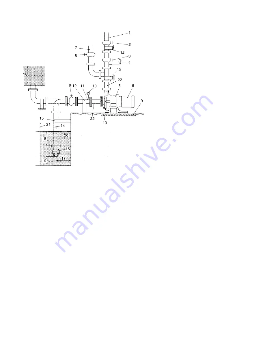
1.  The suction pipe should employ the flooded suction method if possible.  The shortest pipe possible, with

the minimum number of bends, should be designed.  Arrange a proper support on the suction pipe so that
the load and the thermal stress of the pipe itself are not applied to the pump.

2.  Attach the coupling on the suction pipe carefully, so that no air enters the line.  The presence of air in the

suction pipe may prevent priming of the pump.

3.  Avoid installations with poor suction conditions (e.g. vacuum in suction tank, large suction head  or long

suction piping).  NPSHa should always be at least 2 feet greater than NPSHr.  For NPSHr values, refer to
the standard performance curve for your pump model or contact Iwaki Walchem or your distributor.

4.  When using a bend on the suction side, install a straight pipe which is more than 20 inches long or 10

times as long as the suction port diameter before the suction port of the pump. Use the largest possible
radius of curvature for the bend.

5.  Do not allow any projection where air may be trapped along the suction pipe.  The suction pipe should

have an ascending gradient toward the pump.

n

Suction Piping

n

Piping

1.  Discharge pipe (Use a support to keep the

pump free from the load of the pipe.)

2.  Gate valve
3.  Check valve
4.  Pressure gauge
5.  Motor
6.  Pump
7.  Priming pipe
8.  Gate valve
9.  Drain ditch
10. Compound gauge

11. Suction pipe (D=Diameter of pipe) (Shortest

horizontal section with an ascending gradient
toward the pump)

12. Pipe support
13. Pump drain (not applicable to MDH-(F))
14. Suction pipe (D=Diameter of pipe)
15. Suction pipe stabilizer brace (Used if the

suction pipe is particularly long.)

16. Foot valve
17. 1.5D or more
18.18 inches or more
19. 1- 1.5D or more (if sediment accumulates

easily)

20. Suction tank
21. Screen
22. Short pipe

Fig. 4

Содержание MDH-400 Series

Страница 1: ...heck that the pump body and parts have not been accidentally damaged or that any bolts or nuts have not been loosened in transit Thank you for selecting an Iwaki Walchem MDH F Series magnetic drive pu...

Страница 2: ...IWAKI WALCHEM MAGNETIC DRIVE PUMP MDH F SERIES INSTRUCTION MANUAL IWAKI WALCHEM Corporation...

Страница 3: ...Guide 2 3 Specifications 3 4 Handling 5 5 Installation Piping and Wiring 7 6 Operation 11 7 Maintenance and Inspection 14 8 Troubleshooting 19 9 Parts Description and Exploded View 23 10 Disassembly a...

Страница 4: ...401 422 423 425 Bearing Option C R S A C F Bearing Carbon PTFE Carbon Carbon Spindle Alumina Alumina 316 S S Alumina Alumina High Purity Front Thrust Ceramic Ceramic 316 S S Ceramic Ceramic Alumina R...

Страница 5: ...ecific gravity fluids up to 2 0 can be handled with appropriate trimming of impeller Consult Iwaki Walchem or your distributor for recommended model and impeller trim 5 The MDH 401 7 when coupled to a...

Страница 6: ...amic 316 SS Alumina ceramic 99 8 Alumina ceramic Bearing Carbon PTFE Carbon Alumina High density carbon ceramic Mouth Ring PTFE PTFE Thrust Ring Alumina ceramic 316 SS Alumina ceramic 99 8 Alumina cer...

Страница 7: ...at the pump be allowed to cool for at least 20 minutes after dry running before introducing fluid again E Models Pumps identified with E at the end of the model identification cannot endure dry runnin...

Страница 8: ...and capacity of the pump may be lower than in the case of pure water The required driving power may also vary and should be checked 7 Intermittent operation Frequent start stop switching shortens the...

Страница 9: ...easy maintenance n Installation 1 The pump anchoring area must be greater than the area of the pump baseplate If the anchoring area is not large enough the baseplate may be damaged due to the concentr...

Страница 10: ...ll a straight pipe which is more than 20 inches long or 10 times as long as the suction port diameter before the suction port of the pump Use the largest possible radius of curvature for the bend 5 Do...

Страница 11: ...or more below the surface of the liquid 9 A screen should be provided at the inlet of the suction tank to prevent the entrance of foreign matter into the suction pipe Foreign matter may cause malfunct...

Страница 12: ...piping resistance Other wise the specified performance may not be obtained due to increased piping resistance 4 A check valve should be installed if any of the following conditions exists in the pipin...

Страница 13: ...re of liquid in the pump may cause damage to the pump 7 In the event of a service power failure turn off the power switch immediately and close the discharge valve n Wiring Use appropriate wiring mate...

Страница 14: ...round the impeller 6 If using flooded suction measure the pressure in the suction pipe to check that the pump is filled with liquid 7 Run the motor momentarily to check the direction of motor rotation...

Страница 15: ...r is unavailable check values of If pump enters continuous operation discharge pressure suction pressure and current condition check flow meter and confirm in relation to piping resistance that pump o...

Страница 16: ...n of each measurement If the valve re mains open during operation the gauge mechanism may be affected by abnormal pressure caused by water hammer 4 If a spare pump is included in the installation keep...

Страница 17: ...butor if abnormality is observed Replace if abnormality is observed Clean l Is there scoring in rear face or cylindrical body l Are there any cracks in the plastic of the rear section or cylindrical b...

Страница 18: ...s of Spindle Bearing Mouth Ring Impeller Thrust If the difference between Bearing I D and Spindle O D exceeds 0 039 in 1mm either the bearing or the spindle whichever has the greater wear should be re...

Страница 19: ...f the surfaces are worn out beyond the wear limit A the pump is subject to serious damage The condition of the surfaces in contact must be checked if an abnormal operation such as dry running or cavit...

Страница 20: ...102 2 60 039 1 0 5 Physically confirm that clearances are adequate by spinning impeller by hand in rear casing Tips are not worn out beyond wear limit The impeller and magnet capsule rotate smoothly...

Страница 21: ...abnormally low l Magnet coupling is disconnected Stop pump and use a screw driver to check for easy and smooth rotation of motor fan Measure current level to check for low reading Check for foreign ma...

Страница 22: ...ter Needles of pressure gauge and vacuum gauge fluctuate l Air enters via suction pipe or gasket section Check flange gaskets of suction pipe and tighten Vacuum gauge needle indicates high value while...

Страница 23: ...Clock wise when viewed from motor side Check whether voltage and frequency levels are adequate l Overload Check whether specific gravity and viscosity of liquid are above specifi cation Stop pump and...

Страница 24: ...pipe is closed or restricted Cavitation is caused l Wear or melting of pump bushing l Damaged inner magnet assembly or pump spindle l Fluctuating dynamic balance of outer drive magnet assem bly l Wea...

Страница 25: ...outh ring 1 14 Bolt w washers 6 4 Magnet capsule bearing assy 1 15 Bolt w washers 2 6 Bearing 1 16 Bolt w washers 4 7 Rear casing spindle unit 1 17 Flange option 2 10 Drive magnet assy 1 18 O ring opt...

Страница 26: ...sembly 1 Loosen and remove front casing bolts 14 and 15 2 Remove front casing 1 Wash and clean pump inside 3 Remove impeller 2 and magnet capsule 4 from rear casing 7 Magnet capsule should be kept fre...

Страница 27: ...and protrudes from the bottom of magnet capsule Fig 12 Bearing MDH F 422 423 425 1 Separate the impeller from magnet capsule by unscrewing it counterclockwise from impeller side Note If the impeller c...

Страница 28: ...r MDH F models 2 Lift up and remove mouth ring by applying a screwdriver to the bottom of mouth ring 3 Place new mouth ring into impeller properly Align recessed area of mouth ring with mating surface...

Страница 29: ...y using a strap wrench Should the impeller be hard to screw on place magnet capule in hot water approx 194 F 90 C for five minutes then assemble Gap between rear shroud of impeller and top of magnet c...

Страница 30: ...ing information 1 Description and item number according to this instruction manual 2 Pump model number and serial number as shown on the nameplate of the pump 3 Drawing number if you have received a c...

Страница 31: ...Model Connections Series NPTM A E1 HL F H CP O D X Y Z 400 1 x 1 5 51 4 33 5 67 3 86 0 47 8 75 8 27 3 74 4 53 3 19 2 00 140 110 144 98 12 222 210 95 115 81 51 401 1 x 1 6 30 5 12 7 00 5 12 0 47 11 50...

Страница 32: ...10 28 55 x 1 4 12 24 10 59 5 31 5 28 3 27 2 56 260 230 150 261 14 x 36 311 269 135 134 83 65 Model Pump Weights without motor lbs kg 425 44 20 n MDH F 425 Weight Dimensions Note 1 Overall length varie...

Страница 33: ...WALCHEM CORPORATION 5 BOYNTON ROAD HOPPING BROOK PARK HOLLISTON MA 01746 USA TEL 508 429 1440 FAX 508 429 1386 E MAIL IWAKIWALCHEM IWAKIWALCHEM COM ON THE INTERNET AT WWW IWAKIWALCHEM COM P N 180118 H...

Отзывы: