C78 ENT M50
INSTALLATION INSTRUCTIONS
7
FEBRUARY 2003 EDITION
FUEL LINE
charges. The tank shall be provided with a vent to prevent
internal pressure from exceeding ± 5kPa (± 0.5 mmH
2
O).
Fuel tank and suction assembly shall be so shaped as to
assure suction even at the maximum longitudinal and trans-
verse inclination allowed for the boat, with a residual quan-
tity of fuel oil considered “reserves”.
It is recommended to obtain a residual capacity on the bot-
tom of the tank, where the intake inlet should be posi-
tioned, and to use a Venturi inlet cup to prevent the entry
of sludge.The return flow must take place in such a way as
to favor the mixing of returning fuel oil with the fuel oil in
the tank.
Use of metallic pipes, except those made of copper or its
alloys, shall entail connecting each individual segment to the
engine ground or battery negative terminal to prevent the
accumulation of electrostatic discharges, and inserting a
vibration damping elastic junction on each segment.
Installed pipes shall be CE certified.
Pre-filter
The pre-filter with priming pump, supplied separate from
the engine, must be adequately fastened in such a way as to
enable easily to replace the filtering cartridge and/or to
operate the pump.
To avoid introducing impurities in the feeding pipelines
inside the engine, we recommend not installing filtering car-
tridges previously filled with fuel in the system.
Material Characteristics
The fuel tank, the suction and return assembly and the feed
pipes shall withstand the continuous abrasion caused by a
90 l/h flow of fuel oil at a temperature of 80 °C without
noticeable warping, wear, or release of material.
Use of metallic materials, though not copper alloys, is
allowed provided they are connected to the battery’s neg-
ative terminal to avoid the accumulation of electrostatic dis-
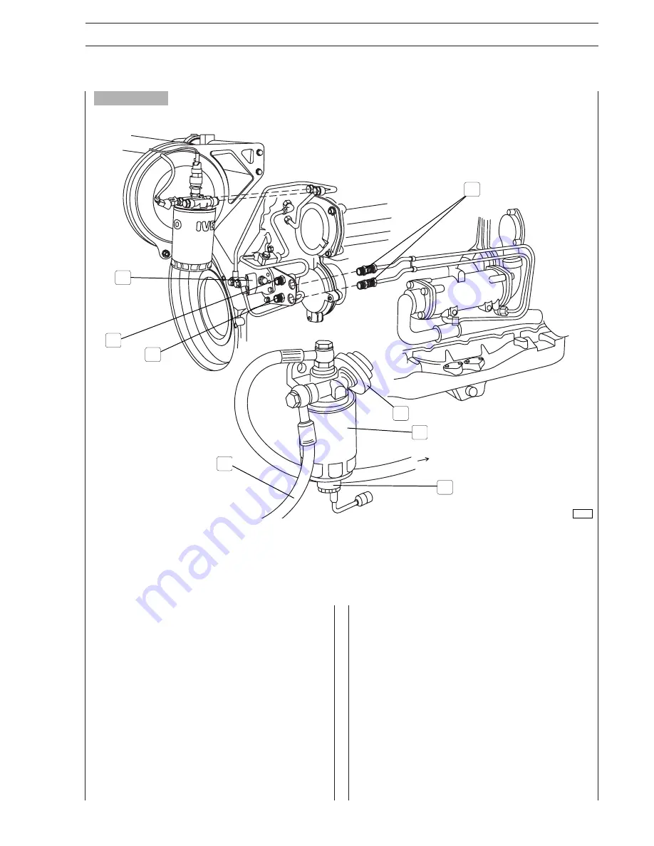
1. From the tank - 2. Sensor for detecting the presence of water in the filter - 3. Decanting filter - 4.Priming pump -
5. Fuel inlet junction - 6. Fuel return junction to tank - 7. Gear pump - 8. Junctions for inverter oil heat exchanger.
Figure 3
3
1
8
7
2
6
5
4
81795
Содержание C78 ENT M50
Страница 1: ...C78 ENT M50 MARINE ENGINE INSTALLATION INSTRUCTION ...
Страница 4: ...C78 ENT M50 IV FEBRUARY 2003 EDITION ...
Страница 6: ...C78 ENT M50 OVERVIEW 2 FEBRUARY 2003 EDITION ...
Страница 34: ...C78 ENT M50 DIAGNOSTICS 2 FEBRUARY 2003 EDITION ...
Страница 37: ...C78 ENT M50 5 FEBRUARY 2003 EDITION NOTES ...
Страница 38: ...C78 ENT M50 6 FEBRUARY 2003 EDITION NOTES ...
Страница 39: ...C78 ENT M50 7 FEBRUARY 2003 EDITION ...


