T
C
(°C)
T
R
(°C)
T
M
(°C)
E
p
(kW)
Bypass
T
C
(°C)
T
R
(°C)
T
M
(°C)
E
p
(kW)
Bypass
40
30
35
16
4 40
30
38
16
1
45
30
35
20
Aperto
Open
45
30
38
25
3 ¼
50
30
35
50
30
38
33
Aperto
Open
55
30
35
55
30
38
60
30
35
60
30
38
65
30
35
65
30
38
70
30
35
70
30
38
75
30
35
75
30
38
40
30
36
16
2 ¼
40
30
39
16
½
45
30
36
25
Aperto
Open
45
30
39
25
2 ¼
50
30
36
50
30
39
33
6 ¼
55
30
36
55
30
39
37
Aperto
Open
60
30
36
60
30
39
65
30
36
65
30
39
70
30
36
70
30
39
75
30
36
75
30
39
40
30
37
16
1 ½
40
30
40
16
Chiuso/Closed
45
30
37
25
5 ½
45
30
40
25
1 ¾
50
30
37
28
Aperto
Open
50
30
40
33
4
55
30
37
55
30
40
41
Aperto
Open
60
30
37
60
30
40
65
30
37
65
30
40
70
30
37
70
30
40
75
30
37
75
30
40
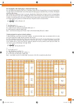
Angaben für Anlagenplaner
Dieser Abschnitt enthält komplette Grafiken für die Komponenten des UNIMIX-Systems (Mischventil und Ausgleichs-Bypass auf der
Sekundärleitung), die bei der Planung von Anlagen helfen sollen, die Systemleistungen genau zu berechnen und das System richtig zu
kalibrieren.
Einstellung des Ausgleichs-Bypass auf der Sekundärleitung:
Der Ausgleichs-Bypass auf der Sekundärleitung ist mit einer doppelten Mikrometereinstellung mit Positionsspeicher (für den Fall vor-
übergehender Abschaltung) versehen. Zur richtigen Einstellung folgendermaßen vorgehen:
1.
Mit einem Schraubenzieher den in der Sechskantöffnung befindlichen Verriegelungsstift herausdrehen und entfernen.
2.
Mit einem 5-mm Stiftschlüssel die große Einstellschraube festdrehen (Abb. Q1)
3.
Den Verriegelungsstift wieder voll eindrehen. Die Einstellposition mit einem “x” markieren (Abb. Q2).
4.
Den Schraubenzieher auf das “x” ausrichten und dann einige Umdrehungen öffnen (Abb. Q3) wie in der Grafik ∆p-Q des
Sekundär-Bypass ersichtlich. (ACHTUNG: Die Anzahl der Umdrehungen entspricht denjenigen des Verriegelungsstiftes!).
5.
Dann die große Schraube bis zum Anschlag losschrauben (Abb. Q4). Die Voreinstellung ist nun durchgeführt und ändert sich
nicht, auch nicht nach wiederholtem Öffnen/Schließen mit dem Stiftschlüssel.
Indications for plant designers:
this section includes complete diagrams of the components in the UNIMIX system (mixer valve and secondary balance bypass) in order
to help designers make accurate calculations of system performances and correct calibration of the system.
Adjustment of the secondary balance bypass:
the secondary balance bypass is fitted with dual creep adjustment with position memory in the event of temporary closure. for correct
adjustment and balancing of the circuit, refer to the following procedure:
1.
Use a screwdriver to back off and remove the lock dowel with notch inside the hexagonal hole
2.
close the large adjustment screw using an Allen wrench of 5 mm (Fig. Q1)
3.
snugly re-tighten the lock dowel with notch. Indicate the adjustment landmark with “x” (fig. Q2).
4.
Align the screwdriver with “x”. Then open by a few turns (fig. Q3) with reference to diagram ∆p-Q detailing the secondary
bypass (CAUTION: the number of turns refers to the number of turns of the creep adjustment dowel!).
5.
Then open the large screw to the locator limit (fig. Q4). Pre-adjustment has now been made and will not change even following
repeated opening/closing using the Allen wrench.
∆p = 150 mbar
IVAR_UNIMIX_E_DE.indd 14
05-11-2008 10:04:47
Содержание UNIMIX
Страница 1: ...UNIMIX IVAR_UNIMIX_E_DE indd 1 05 11 2008 10 04 07 ...
Страница 17: ...IVAR_UNIMIX_E_DE indd 17 05 11 2008 10 04 53 ...
Страница 18: ...IVAR_UNIMIX_E_DE indd 18 05 11 2008 10 04 57 ...
Страница 19: ...IVAR_UNIMIX_E_DE indd 19 05 11 2008 10 04 58 ...


