background image

4

PG 1-R1

Issued 05/01

Figure 4

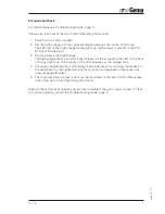
Preparatory steps for initial start-up

For operating the PG 1-R1 Robot Powder Gun observe absolutely
the relevant Safety Notice, and the Safety Instructions of the Robot
manufacturer!

a) Connecting the PG 1-R1 Powder Gun

1. Fit the gun on the adapter on the Robot arm .

Make sure that the pin on the adapter sits exactly in the slot in gun flange.

2. Tighten the fixing screw (also take note of the assembly instructions of the Robot

manufacturer).

3. Position the gun cable, powder, and rinsing air hoses on the inside the arm so that

neither kinks nor twists can form.

4. Connect the gun cable to the gun control (See the Gun Control Operating Instructions)

5. Connect the rinsing air hose from the corresponding connection to the gun.

6. Connect the powder hose from the gun to the corresponding Injector.

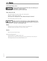
CAUTION

Powder hose - PI Injector

Rinsing air - Gun Control

Gun cable - Gun Control

Содержание PG 1-R1

Страница 1: ...17 PG 1 R1 Issued 05 01 Operating Instructions and Spare Parts List PG 1 R1 Robot Powder Gun E ...

Страница 2: ...18 PG 1 R1 Issued 05 01 ...

Страница 3: ...tart up 4 a Connecting the PG 1 R1 Powder gun 4 b Functional check 5 Start up 6 a Adjusting the powder output and powder cloud 6 b Powder coating Start up 6 c Shut down 6 d Rinsing the powder hose 6 Maintenance schedule 7 a Daily maintenance 7 b Weekly maintenance 7 Cleaning and repairs 7 PG 1 R1 Powder Gun 7 a Cleaning 7 b Gun dismantling 8 c Gun assembly 9 e Cleaning the Spray nozzles 10 Trouble...

Страница 4: ...20 PG 1 R1 Issued 05 01 ...

Страница 5: ...ssary Adapter for the corresponding Robot type by means of a pin for the exact positioning of the gun and also a carrier for the gun cable and hoses 8 3 4 7 9 6 1 2 16 10 11 12 15 8 Support 9 Flange plate 10 Locking screw 11 Gun cable connection 12 Gun cable 15 Powder hose connection 16 Rinsing air connection 1 Atomizing system 2 Threaded sleeve 3 Shaft 4 HV cascade 5 End plate 6 LED window 7 Plas...

Страница 6: ...stages in the cascade d until the required high voltage is attained The high voltage is then fed from the spray nozzle to the electrode e See Figure 3 When the high voltage is adjusted on the control module the intensity of the LED 6 also changes The user has the assurance that high voltage is present and has control over this function Figure 2 2 Powder flow and supplementary air The supplementary...

Страница 7: ...ted inside the gun is conducted via the black contact ring of the nozzle holder to the centre electrode High Voltage Rinsing air Rinsing air e Figure 3 In order to prevent powder from sintering on the electrode the latter is cleaned by com pressed air during the spraying process For this purpose rinsing air is fed via the small hole in the black contact ring in the nozzle holder into the hole in t...

Страница 8: ...in the slot in gun flange 2 Tighten the fixing screw also take note of the assembly instructions of the Robot manufacturer 3 Position the gun cable powder and rinsing air hoses on the inside the arm so that neither kinks nor twists can form 4 Connect the gun cable to the gun control See the Gun Control Operating Instructions 5 Connect the rinsing air hose from the corresponding connection to the g...

Страница 9: ...ge reading should slowly increase At the same time the LED on the back of the gun lights up The intensity of the LED increases as the voltage rises 4 Conveying Supplementary and Rinsing air pressure are set accordingly dependent on the application by the higher hierarchy Plant control and displayed on the respective pressure gauge Display 5 The maximum Rated output current can be monitored on the ...

Страница 10: ... affected b Start up Powder coating First check that all electrically conducting parts within 5 m of the coating booth are grounded 1 Switch on the control module 2 Adjust the High Voltage Check by observing the LED 6 c Shut down 1 Switch off the control module The settings for High Voltage rinsing air and powder output can be left as they are 2 For interruptions in working such as lunchbreaks ove...

Страница 11: ... conveyor chain Cleaning and repairs PG 1 R1 Powder Gun a Cleaning Frequent cleaning of the gun is recommended to assure good coating quality Before cleaning the gun switch off the control module and detach the gun connector The compressed air used for cleaning should be free of oil and water Daily 1 Clean the outside of the gun Weekly 2 Detach the powder hose at the connector 3 Detach the nozzle ...

Страница 12: ...cess to the corre sponding part is achieved Before cleaning the gun switch off the control module and detach The cascade must not be removed because it has been installed according to a special process If the cascade is defect send the entire shaft 3 to an authorized ITW Gema service centre Figure 5 8 1 7 5 3 20 16 9 20 15 25 26 12 23 23 22 22 22 10 8 21 1 2 28 19 IMPORTANT ...

Страница 13: ...ns for the powder hose 15 and the rinsing air 16 should not be unscrewed if they are not defect c Gun assembly The gun is reassembled by performing the previously described dismantling steps in the reverse order Careful handling is recommended If the gun cable connector cannot be inserted properly without applying force disas semble the gun again and reassemble it The Powder hose connection 15 sho...

Страница 14: ...ating of the spray nozzle Make sure that the threaded sleeve is always tightened correctly If the flat jet nozzle is loosely fitted high voltage from the gun can flash over and damage the gun Weekly Remove the spray nozzles and clean the inside with compressed air Sintered powder accumulations should also be removed Monthly Check the spray nozzles for wear Replace the flat jet nozzle if the spray ...

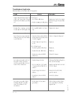
Страница 15: ...igh voltage display does not show any value even though theControlmoduleisswitched on During the spraying process air escapes from the gun shaft Gun does not spray powder although the Control module is switched on Gun sprays powder LED at the rear of the cascade is not lit powder does not ad here to the workpiece Gun sprays powder High Voltage present powder does not adhere to the workpiece Remedi...

Страница 16: ...12 PG 1 R1 Issued 05 01 NOTES ...

Страница 17: ...cable or hose material the lengths required must also be given The spare part numbers of yard metre ware always begins with 1 and are always marked with an in the spare parts list Wear parts are always marked with a All dimensions of plastic powder hoses are quoted as external o d and internal i d diam eters e g ø 8 6 mm 8 mm outside diameter o d 6 mm inside diameter i d For optimum coating qualit...

Страница 18: ...age cascade in the shaft is defect then the complete shaft must be returned to an ITW Gema service centre to be in spected and or repaired The High Voltage cascade is fitted according to a special process and therefore should not be dismantled by the user 3 If the gun cable 12 is defect the complete gun cable assembly should be returned for repair Figure 6 8 1 7 5 3 20 16 9 20 15 25 26 12 23 23 22...

Страница 19: ...64 8 1 Air tube 650 072 9 Flange plate 650 110 9 1 Cylinder scew M 5 x 30 mm for Item 9 216 372 10 Grub screw M 4 x 30 mm 600 342 12 Gun cable complete 20 m 651 400 12 1 Cable only for Item 12 102 911 15 Powder hose connector Aluminium with O ring Item 20 653 136 16 Rinsing air connector 328 820 19 Powder tube 653 101 20 O Ring ø 13 1 x 1 6 mm 600 326 21 O Ring ø 6 1 x 1 6 mm 600 334 22 O Ring ø 7...

Страница 20: ...rks or registered trademarks of their respective holders Reference is made in this manual to different trademarks or registered trademarks Such references do not mean that the manufacturers concerned approve of or are bound in any form by this manual We have endeavoured to retain the preferred spelling of the trade marks and registered trademarks of the copyright holders To the best of our knowled...

Отзывы: