Function overview
Page 59
Homing can be started by way of a command via the communication interface or automatically when the controller is enabled.
Optionally, it is also possible to configure the start via a digital input by way of the item Motion Soft
parameterisation software
in order to perform a homing process in a targeted manner regardless of whether the controller has been enabled or not.
Among other things, the controller enable acknowledges error messages (with a falling edge), for example, and can be
switched off depending on the application without requiring another homing operation when the controller is enabled once
again. Since the existing digital inputs are all used in the case of standard applications, the analogue inputs AIN 1 and AIN 2
can optionally be used as digital inputs DIN AIN 1 and DIN AIN 2, and the digital outputs DOUT 2 and DOUT 3 as digital inputs
DIN 10 and DIN 11.
For homing, several different methods have been implemented following the DSP 402 CANopen protocol. Most methods
usually try to locate a switch at search speed. The subsequent movement depends on the method and type of communication.
If a homing process is activated via the fieldbus, there will be no follow-up positioning to the zero position. This can be done
optionally during the start process via controller enable or RS232. A follow-up positioning run is always possible as an option.
The default setting is "no follow-up positioning run".
It is possible to parameterise ramps and speed values for the homing run. Homing can also be performed in a time-optimal or
jerk-free manner.
5.3.6
Positioning sequences
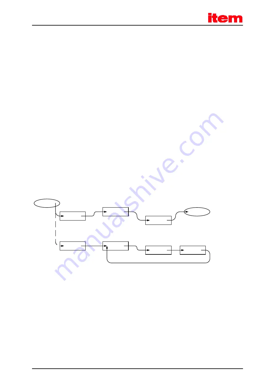
Positioning sequences consist of a series of position sets. These are completed one after the other. A position set can become
part of a path program. The result is a linked list of positions:
POS1
POS13
POS19
START
END
POS5
POS6
POS7
POS8
Figure 4:
Path program
The user defines the position sequence that is to be performed via the start position of the path program. Linear or cyclic
sequences are possible.
The start position of a path program can be defined:
via fieldbus
via digital inputs
The number of positions in a positioning sequence is limited only by the total number of available positions. Every user-defined
position set (0 to 255) can be used in the path program.
For further information, please refer to the software manual "item Servo Positioning Controller C Series".
Содержание C 3-Series
Страница 12: ...Page 12 Figure 33 Servo positioning controller with an integrated technology module 160 ...
Страница 70: ...Mechanical installation Page 70 Figure 8 item Servo Positioning Controller C 3 Series installation space ...
Страница 71: ...Mechanical installation Page 71 7 2 Device view Figure 9 item Servo Positioning Controller C 3 10 front view ...
Страница 76: ...Electrical installation Page 76 Figure 14 Complete set up of the item C 3 Series with a motor and PC ...


